







Limiting drawing ratio (LDR) is the largest blank diameter successfully drawn into a cup divided by the punch diameter, for the stated material and test setup. A proposed part’s blank-to-punch ratio is a calculation; it becomes evidence of a limiting ratio only through an appropriate test and documented acceptance criteria. [1] WorldAutoSteel. Use the calculation to frame a feasibility review before committing to a stamping die.
This guide answers an OEM tooling engineer’s practical question: what does a cup ratio establish, and what evidence is still needed before approving the forming route? It provides an explicit diameter convention, checked geometric examples and a worksheet connecting the calculation to material, tooling and inspection records.
What does limiting drawing ratio actually measure?
In cylindrical cup drawing, the flange feeds toward the die opening while experiencing radial tension and circumferential compression. The cup wall transmits the drawing load. WorldAutoSteel describes these conditions and the cup test used to establish drawability. [1] WorldAutoSteel. This mechanism explains why the review concerns controlled material flow rather than simply stretching a circular sheet into a container.
The Swift cup test is a method for assessing sheet-metal deep drawability; ZwickRoell describes its endpoint in terms of forming a cup without cracking. [3] ZwickRoell. Before commissioning a test, agree what constitutes a successful specimen, how it is inspected and how a limiting result will be reported. A photograph of an apparently intact cup is an incomplete record if the relevant inspection and setup information are missing.
Draw ratio and limiting ratio answer different questions
For this guide, write the proposed ratio as β = D/dp, where D is circular blank diameter and dp is punch diameter. Write the tested limit as LDR = Dmax/dp, where Dmax is the largest successfully drawn blank under the documented conditions. Both are dimensionless when the diameters use matching units. The punch convention follows WorldAutoSteel and ERICHSEN’s explicit key-figure equation. [1] WorldAutoSteel; [2] ERICHSEN.
Suppose an engineer proposes D = 80 mm and dp = 40 mm. The calculated ratio is 2.000. That number records geometry, not a successful draw, an approved stage count or a material limit. Keep a separate field for the tested limit, and leave it unverified when no relevant evidence exists. This simple separation prevents a calculated value from being copied into a quotation as though it were a proven capability.
Define blank, punch and cup diameters
Document the denominator with a sketch or the tool drawing. Do not substitute the die opening, finished outside diameter or mean wall diameter without declaring the change. Some supplier summaries use “die diameter” in their narrative; ERICHSEN’s calculation section explicitly defines the denominator as punch diameter, while ZwickRoell’s brief summary uses die terminology. [2] ERICHSEN; [3] ZwickRoell. A comparison should therefore retain the actual dimension definitions alongside the number.
As a dimensional teaching example, imagine a punch diameter of 40.0 mm and a separately specified die opening of 42.2 mm. With an 80.0 mm blank, 80.0/40.0 = 2.000, whereas 80.0/42.2 = 1.896. The difference comes entirely from changing the reference. The invented 42.2 mm opening is not a clearance recommendation, and neither calculation predicts whether the hypothetical sheet can be formed.
For each source or supplier report, request the blank drawing, punch reference, sheet thickness, tool revision and test method. If the denominator is unclear, mark the result as not directly comparable until clarified. Do not silently normalize a published ratio using a guessed diameter. An unexplained extra decimal place cannot repair an ambiguous definition.
Estimate blank diameter from an idealized cup
A preliminary deep drawing blank diameter can be derived by equating idealized surface areas. Define a mathematical cup with a flat circular base of diameter d, straight wall height h, no flange and zero corner radius. Assume constant thickness, no trimming allowance and no material loss. This is a thin-surface model: d is its representative surface diameter, not automatically the actual punch or finished outside diameter.
The blank area is πD²/4. The modeled base area is πd²/4 and wall area is πdh. Equating these areas gives πD²/4 = πd²/4 + πdh, and therefore D = √(d² + 4dh). This result follows from the declared geometric assumptions. It is not a sourced material property, a toolmaker’s blank prescription or a substitute for a realistic forming model.
For hypothetical d = 40 mm and h = 30 mm, D = √(1600 + 4800) = 80.000 mm. Both areas equal 1600π mm², approximately 5026.548 mm². The equality checks the derivation and arithmetic. It does not show that the material can move into the modeled shape without fracture, wrinkles, unacceptable thinning or an unsuitable rim.
| Surface diameter d (mm) | Height h (mm) | d² + 4dh (mm²) | Calculated D (mm) |
|---|---|---|---|
| 40.0 | 20.0 | 4800 | 69.282 |
| 40.0 | 30.0 | 6400 | 80.000 |
| 40.0 | 40.0 | 8000 | 89.443 |
The table isolates height sensitivity within the same mathematical model. Increasing the hypothetical height from 20 to 40 mm changes the calculated blank from 69.282 to 89.443 mm, approximately 29.10%. This is a geometric comparison only. A practical blank must be reviewed against the actual surface geometry, trim strategy and forming route before it is issued for cutting.
In a project worksheet, retain separate entries for the estimated blank, the proposed trial blank and the final approved blank. Explain each revision. If the model includes a flange, rounded base, nonuniform thickness or intermediate draw, rebuild the geometry and route assessment rather than adding an unexplained allowance to this simplified formula.
Compare draw ratios without inventing a safe limit
The following deep drawing ratio calculation holds the hypothetical punch at dp = 40 mm and varies blank diameter. Define diameter reduction for this worksheet as R = 100(D − dp)/D = 100(1 − 1/β). This is a restatement of the dimensions, not percentage wall thinning, strain or a permissible material reduction.
| Blank D (mm) | Punch dp (mm) | β = D/dp | Calculated diameter reduction (%) |
|---|---|---|---|
| 72.0 | 40.0 | 1.800 | 44.44 |
| 76.0 | 40.0 | 1.900 | 47.37 |
| 80.0 | 40.0 | 2.000 | 50.00 |
| 84.0 | 40.0 | 2.100 | 52.38 |
At D = 80 mm, the ratio is 2.000 and the defined diameter reduction is 50.00%. Increasing D to 84 mm raises the ratio to 2.100 and the reduction to 52.38%. Neither row answers whether one draw is feasible. Do not treat the familiar appearance of a ratio near two as a release criterion.
WorldAutoSteel identifies lubrication, blank-holder load, die radius and other system inputs as influences on the absolute limiting ratio. ERICHSEN cautions that one test cannot generally predict suitability across the diversity of formed geometries. [1] WorldAutoSteel; [2] ERICHSEN. Accordingly, this guide supplies no universal safe-ratio chart for steel, stainless steel or aluminum.
Keep a redraw schedule separate from the first-draw limit
ERICHSEN expresses total drawing ratio as the product of successive ratios. [2] ERICHSEN. For a purely hypothetical diameter sequence of 90 → 60 → 45 mm, the arithmetic ratios are 1.500 and 1.333333; their product is 2.000, equal to 90/45. This identity verifies bookkeeping only. It does not approve either stage, an annealing treatment, the intervening geometry or a production route.
Build a feasibility evidence worksheet
Use the proposed worksheet below to turn an isolated ratio into an engineering question with evidence requirements. The material and process fields should identify actual records; “standard steel” and “normal lubrication” are insufficient descriptions for this review. Normal anisotropy is relevant to cup drawability in WorldAutoSteel’s discussion, but it should not be converted here into an invented acceptance value. [1] WorldAutoSteel.
| Review item | Record or units to request | Decision it supports |
|---|---|---|
| Geometry and reference | D, dp, thickness and radii in mm; drawing revision; flange and trim state | Confirm that the compared ratio describes the intended operation. |
| Material identity | Grade, condition, coating, lot and certificate; relevant supplier forming data | Check whether available evidence represents the proposed stock. |
| Tool and machine setup | Tool revision; approved holder load in kN or pressure in MPa with its area basis; speed units and profile | Identify the setup actually associated with the trial result. |
| Interface condition | Lubricant identity/application method; tool surface condition; permitted changes | Make comparisons traceable without assuming equivalent friction. |
| Specimen outcome | Individual cup ID, crack/wrinkle observations, thickness and dimensional records | Separate crack-free drawing from complete component acceptance. |
| Release decision | Approved requirements, unresolved issues, evidence owner and retest trigger | State precisely what is approved and what remains open. |
Agree the inspection stage and acceptance method before testing. The Open University describes the peripheral blank holder and its role in wrinkle prevention. [4] Open University. For this proposed review, include wrinkles in the observation record rather than judging a cup solely on whether it cracked. Specify which surfaces and dimensional features must be checked after trimming or later operations.
Local thickness acceptance is a related but separate question. Use the stainless-cup wall-thinning inspection study for a location-based teaching example. A successful ratio test does not, by itself, provide the component’s minimum-wall record or its functional acceptance decision.
Plan a controlled drawing trial
The following is a proposed planning sequence for the responsible tooling, material and quality teams. Establish an approved baseline, assign unique specimen IDs and retain the tool/material/setup record with every result. Choose a test method and inspection criteria suitable for the intended decision; this article does not reproduce a standard or establish a mandatory sample size.
For an illustrative log, suppose a 40 mm punch is used with 76, 78, 80 and 82 mm blanks, with three specimens planned at each diameter. That is 4 × 3 = 12 specimens. The ratios are 1.900, 1.950, 2.000 and 2.050. These quantities are invented to explain recordkeeping, not a statistically justified qualification plan or instructions to run an unreviewed tool.
If all assumed 80 mm specimens met the agreed cup-test criterion and all assumed 82 mm specimens failed it under unchanged conditions, the log would bracket the transition between tested ratios 2.000 and 2.050. It would not locate an exact continuous threshold or establish production reliability. Record the largest successful tested blank and the next failed tested blank instead of reporting a falsely precise limiting value.
If outcomes are mixed at one diameter, preserve every specimen result and investigate the variation. Do not select the best cup and silently discard the rest. If the team changes lubrication, holder load, radii or another setup condition, treat the comparison as a new identified condition. This proposed rule protects the meaning of the conditional result rather than treating all cups as interchangeable.
Decide what is ready for tool release
Before authorizing tool manufacture, identify whether the available evidence justifies a concept review, a trial route or an approved component. Use explicit dispositions such as “geometry calculated; material evidence pending” or “trial route approved subject to named inspections.” A ratio alone should not be rewritten as a promise of production capability.
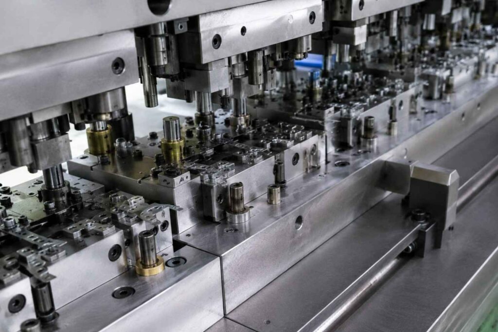
For a discussion with SSP Precision’s tooling team, provide the part drawing, material specification, expected blank basis and the feasibility worksheet. Use the stamping-die product overview when considering the physical tooling configuration. Use the stamping-die manufacturing service to frame the design, build and trial scope. Request project-specific evidence for the intended route.
Keep the calculation file, trial records and approved revisions together. Identify which changes require renewed review, including material condition, thickness, geometry and process setup. The reader’s useful output is a traceable feasibility question and evidence plan, with unresolved assumptions visible before a purchase or release decision.
Frequently asked questions
How do you calculate limiting drawing ratio for a cylindrical cup?
Under the convention used here, divide the largest successfully drawn blank diameter by punch diameter. Without relevant successful test evidence, D/dp is a proposed draw ratio, not an established limit. [1] WorldAutoSteel.
Is a drawing ratio of 2.0 always safe?
No universal approval follows from that number. It describes, for example, an 80 mm blank divided by a 40 mm punch. The worksheet still requires the relevant material, setup and acceptance evidence.
Can blank diameter be calculated from cup height?
Height and a declared surface diameter can provide an idealized estimate: D = √(d² + 4dh) under this guide’s constant-thickness, zero-radius, unflanged model. Actual blank release requires review of the features excluded by that model.
Does a cup test prove a rectangular housing will draw?
No. ERICHSEN cautions that a single method cannot establish general drawability across varied geometries. Use component-specific evidence for the housing’s relevant forming and inspection requirements. [2] ERICHSEN.
Does this article report an SSP drawing test?
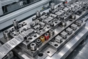
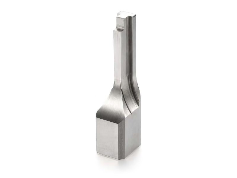
No. All calculations and specimen-log examples are illustrative. The photograph supplies tooling context only. Real feasibility and acceptance claims require the corresponding project records.
Technical references
Reviewed 4 November 2026. Sources support the specific definitions and mechanisms cited nearby. No broad supplier ratio limit is adopted as a universal specification; no standard edition or test procedure is claimed from a summary page. Geometry and specimen counts are explicitly hypothetical.