








Precision micro injection molding
Small plastic components, engineered around your drawing, material and assembly requirements. From micro tooling review to approved samples and repeat supply.
Component types Connector housings, micro gears, optical carriers and other miniature plastic parts.
For a focused quote, share your CAD, critical dimensions, resin and estimated quantities.
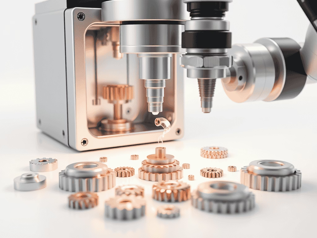
Small parts. Detailed engineering.
Micro molding applies injection molding to miniature plastic components and fine functional features. Successful production depends on how the resin, cavity, filling, ejection and measurement method work together.
At SSP, start with the features that matter in your assembly. We review moldability, tooling access and inspection requirements before defining a manufacturing route. Tolerances, lead times and acceptance evidence are agreed for the individual project.
Micro molding services built around the part
Engineering and procurement need the same clear scope. Define what is being molded, how it interfaces with other components and what evidence is needed for approval.
Micro tooling and DFM
Review thin walls, ribs, fine cores, parting lines, gates and venting. Plan ejection and replaceable tooling features around the geometry before committing to a mold.
Precision component molding
Evaluate small housings, gears, carriers and functional details against the specified resin and use conditions. Treat filling, shrinkage and handling as connected manufacturing decisions.
Insert and assembly interfaces
Identify any metal inserts, contact locations, sealing faces and mating features. Review insert positioning, flash limits and the tests needed to demonstrate fit or retention.
Samples to repeat production
Define the sample approval plan, drawing revision, inspection scope and packing requirements. Use the approved requirements as the reference for subsequent orders.
Micro molded products and tooling
Illustrative component examples, including generated product images. These are custom manufacturing references, not stock items or verified customer projects.
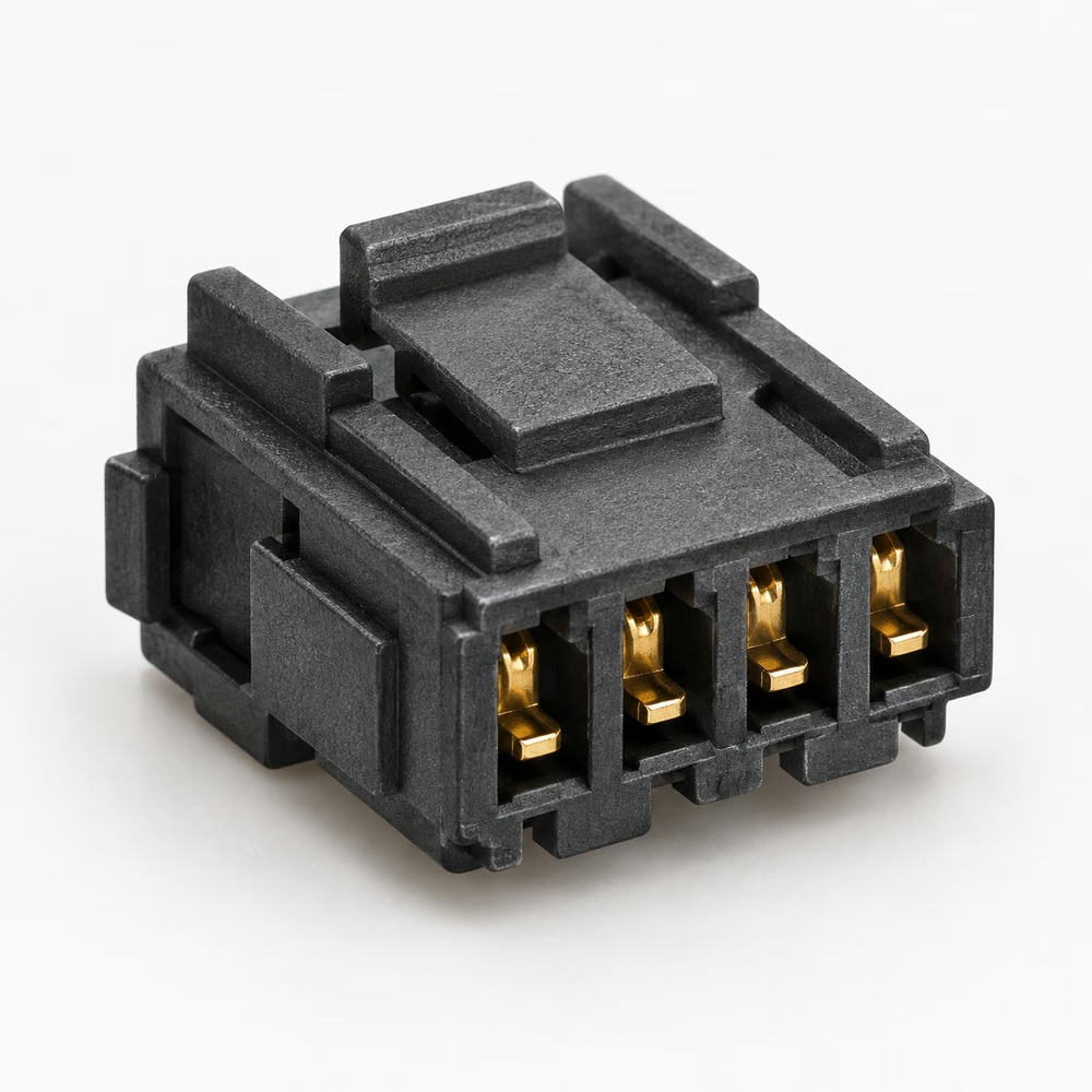
Micro connector housings
Contact pitch, terminal location and flash control at mating interfaces.
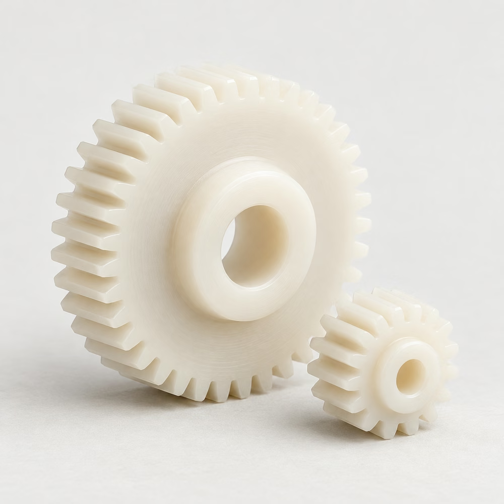
Precision micro gears
Tooth geometry, concentricity and running clearance in the assembly.
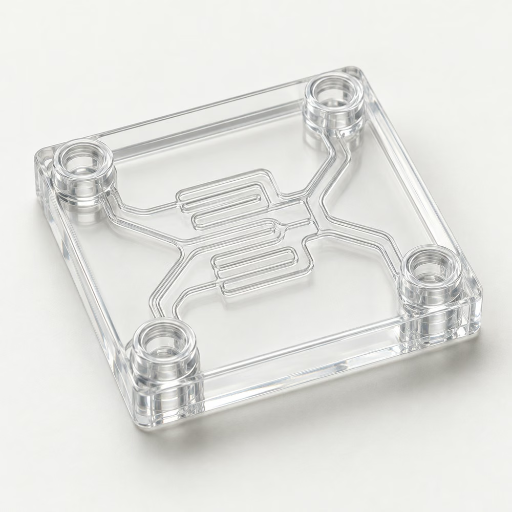
Microfluidic cartridges
Channel geometry, sealing surfaces and application-specific material requirements.
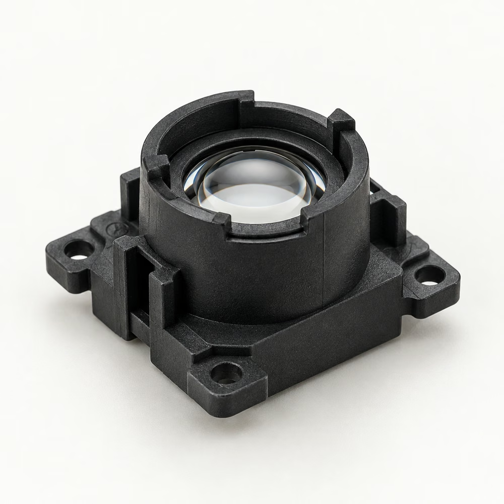
Optical lens carriers
Lens location, datum features and surfaces that must stay free of contamination.
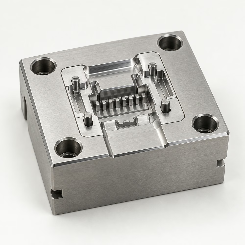
Micro mold inserts
Fine cavity features, tool alignment and maintenance of wear components.
From critical features to controlled supply
A connected service flow with a defined review point at each handover. Scope, sequence and deliverables are confirmed for your micro molding project. Tooling images include generated illustrations.
Review the part and application
Share CAD, a dimensioned drawing, assembly conditions and expected quantities. Identify critical features and any requirements beyond dimensional inspection.
Defined manufacturing scope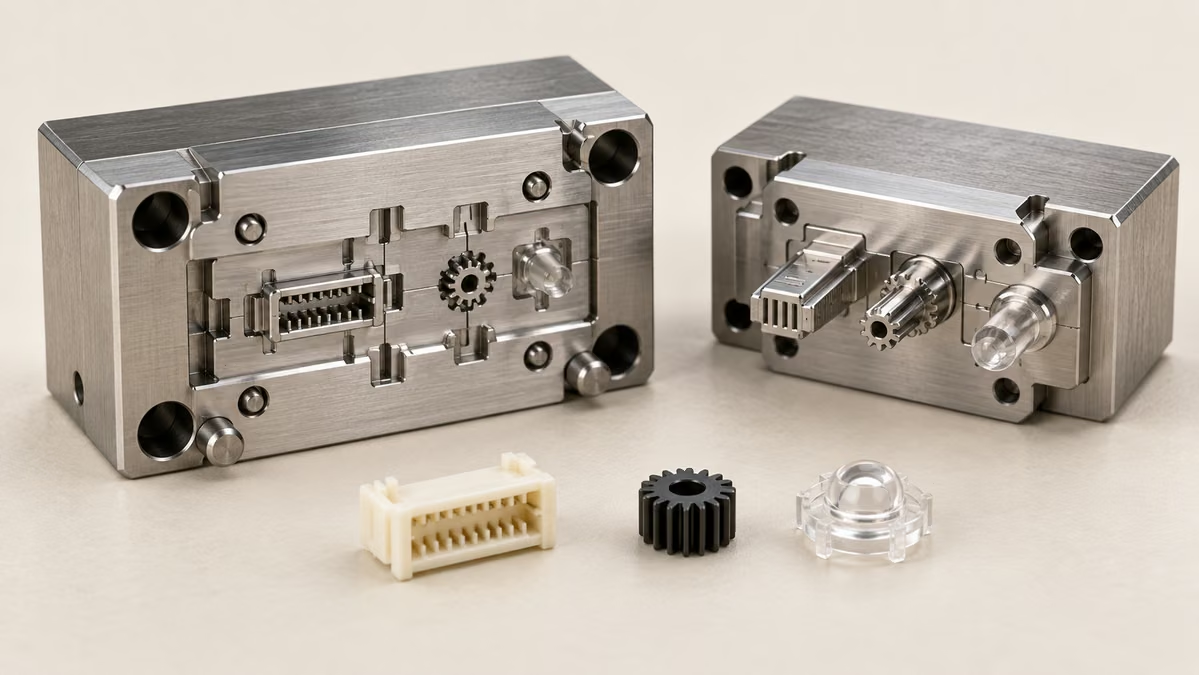
Resolve material and moldability
Review the commercial resin grade, flow paths, wall transitions, gates and ejection. Discuss shrinkage, conditioning and any features that need design adjustment.
Agreed material and DFM actions
Engineer the micro tooling
Review cavity details, fine cores, alignment, cooling and replaceable inserts. Match the tooling concept to the geometry and intended production demand.
Tooling design reviewMold and evaluate samples
Assess filling, flash, deformation and part handling using the agreed material. Record trial findings and corrections before final sample approval.
Samples and correction record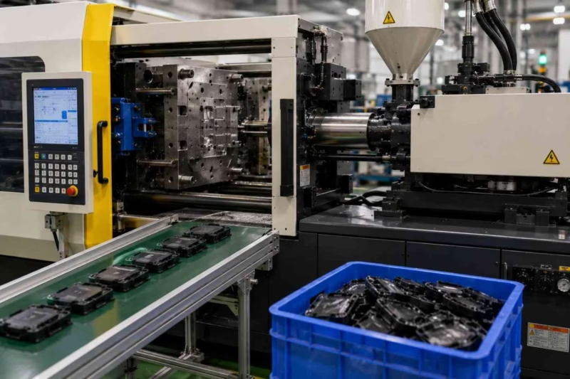
Verify dimensions and function
Agree datums, measurement access, inspection conditions and acceptance limits. Review assembly fit or functional checks where the project requires them.
Approved inspection baseline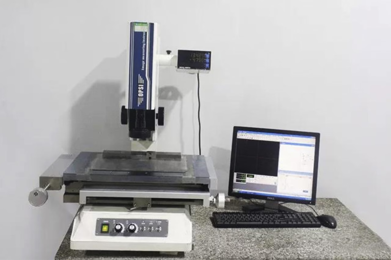
Release production and delivery
Confirm revision, quantity, identification, handling and protective packing. Agree the inspection documents and delivery terms with the order.
Repeat supply to agreed requirements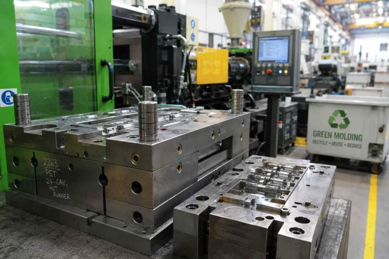
Select the resin. Define the tolerance.
A polymer family is a starting point. Exact grade, geometry, conditioning and application requirements determine the appropriate processing and verification plan.
| Material route | Examples for review | Engineering focus |
|---|---|---|
| Engineering thermoplastics | POM, PA, PBT | Stiffness, wear, moisture response and dimensional stability. |
| Specialist grades | LCP, PPS, PEEK | Flow through fine features, temperature exposure and grade-specific processing. |
| Transparent grades | PC, PMMA, COC / COP | Clarity, molded stress, surface quality and the actual optical requirement. |
Inspect what your assembly depends on
A small part needs a practical inspection strategy. Define how the important features will be measured and accepted before the production order is released.
Critical dimensions
Agree datums, feature access and the measurement method for small holes, walls, pitch and mating surfaces.
Sample approval
Link the dimensional report, appearance criteria and functional checks to the correct drawing revision.
Handling and cleanliness
Specify contamination limits, separation and packaging where delicate features or sensitive surfaces require protection.
Repeat-order control
Confirm material identification, approved changes and the records required with each delivery.
Surface and secondary requirements
Define these before tooling approval so the cavity surface and part handling support the finished component.
Molded surface
Specify functional, cosmetic and optical faces separately, including where gates or ejector marks are acceptable.
Secondary operations
Discuss trimming, cleaning, assembly or identification as a defined scope. Confirm access and the effect on fine features.
Application verification
Agree any sealing, electrical, wear or sterilization compatibility tests. Material supplier data alone does not validate the finished part.
Tooling support around your component
Explore the related manufacturing services for the mold, insert interfaces and maintenance parts.
Before you request a micro molding quote
What do you need to evaluate a micro molded part?
Send the CAD model and drawing revision, resin grade if known, critical dimensions, intended use, sample quantity and expected annual demand. Include inserts, secondary operations and packing requirements.
Can you quote a drawing with very tight tolerances?
Yes, submit it for engineering review. Feasibility is assessed feature by feature against the resin, geometry, tooling and measurement approach. Confirm the accepted limits in the quotation and drawing before ordering.
Which materials are suitable for micro injection molding?
The choice depends on flow, stiffness, wear, moisture, temperature and the application. Discuss an exact commercial grade rather than relying on a polymer name alone; not every grade is suitable for fine features.
Can you support medical or optical applications?
Share the specific application and required evidence for review. A medical or optical use does not automatically establish regulatory compliance, biocompatibility, optical performance or sterilization compatibility.
How are tooling and repeat part orders quoted?
Define tooling, trials, samples, part supply and any inspection or secondary work separately. Lead time, minimum order quantity, tool ownership and delivery terms are confirmed against the agreed project scope.
Give the small details a clear manufacturing plan.
Send your drawing and requirements to discuss the right micro molding route with SSP.
- CAD and drawing revision
- Resin and use conditions
- Critical features and tests
- Sample and annual quantities