







SSP · Have a drawing ready?
Robotics Spare Parts
Custom machined components for robotic systems. Review materials, critical fits, surface finishes and inspection requirements with SSP before manufacture.
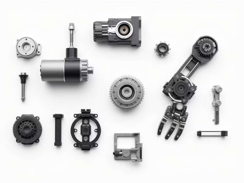
End-effector and handling components for your assembly.
Rail and carriage interfaces for precision movement.
Screw, nut and support components for motion systems.
Related Products
Explore components for industrial robotics and automation. Share the drawing, material, mating interfaces and operating conditions so we can review the right manufacturing scope.
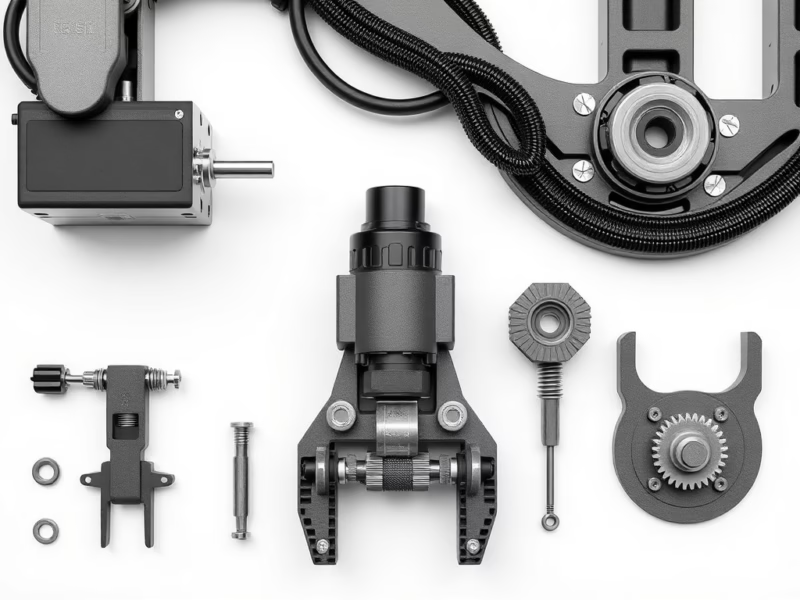
Robotic Gripper Components
End-effector and handling components for your assembly.
Request a quote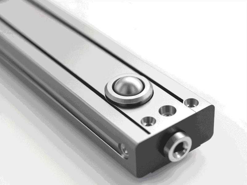
Linear Guide Components
Rail and carriage interfaces for precision movement.
Request a quote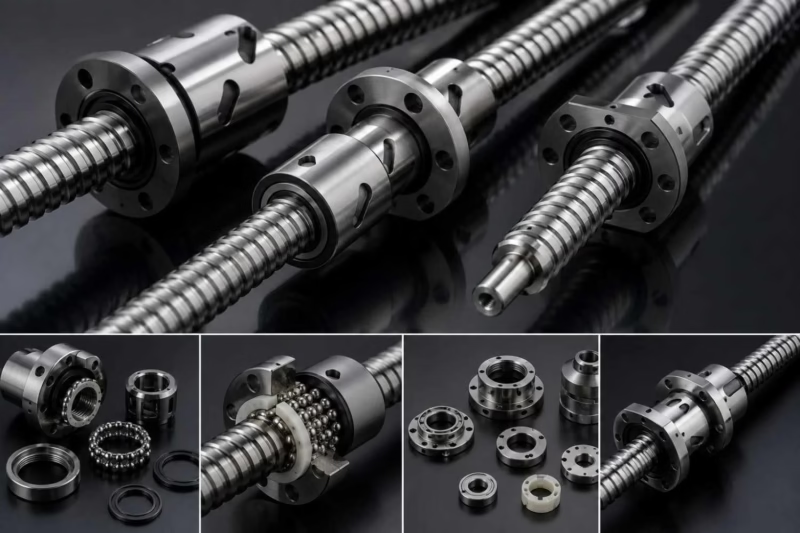
Ball Screw Components
Screw, nut and support components for motion systems.
Request a quote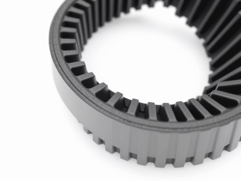
Precision Ring Gears
Drive profiles and mating interfaces made to specification.
Request a quote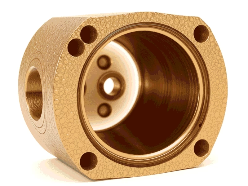
Bronze Bushings
Wear interfaces with application-specific fits and lubrication.
Request a quote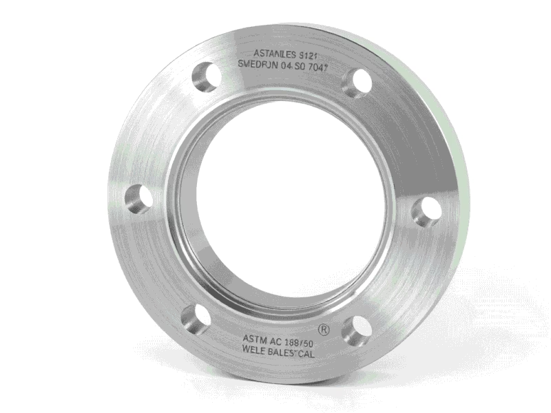
Precision Flanges
Mounting faces and bolt patterns for repeatable assembly.
Request a quote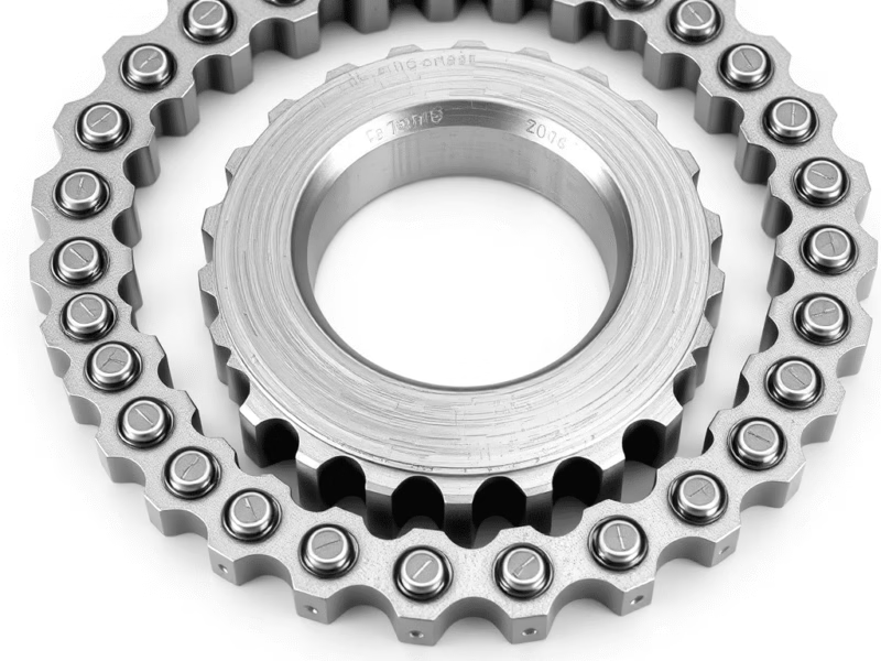
Drive Sprockets
Transmission components for industrial automation.
Request a quoteRobotic Drive Components
Machined components for servo and reducer assemblies.
Request a quote
Made to your drawing
Your specification, reviewed before manufacture.
Drawing · material · quantity
Beyond the catalog
Your part,made to your drawing
Need a custom gripper detail, shaft, bushing or mounting interface? Send the component drawing and mating-part information. Send SSP a STEP model or a dimensioned drawing, together with your material, quantity and inspection requirements. Our team can review the geometry, manufacturing route and quotation scope for your project.
- Drawing or sample review before the manufacturing route is agreed.
- Material, treatment and finish matched to the approved specification.
- Critical dimensions and inspection records defined with your order.
- Prototype, trial and repeat-production needs reviewed for your project.
- NDA available on request.
High-Wear Parts.
Higher Standards.
Industrial robotics spare parts are specialized components designed to maintain and restore automated systems. Precision parts manufactured to meet or exceed approved OEM specifications support integration and reliable operation in demanding production environments.
Keep your robots running at peak performance with components engineered for robotic reliability. Review high-wear interfaces early to minimize downtime and maximize uptime.
High-Performance Servo Systems
Precision motors and reducers with reinforced bearings support consistent torque and positioning accuracy. Confirm the motor, reducer and mechanical interface requirements for your robot.
Durable End Effectors
Ruggedized grippers and tool changers are engineered for millions of operational cycles. Define payload, gripping force, duty cycle and the acceptance test for your application.
Precision Motion Components
Linear guides and ball screws with micron-level tolerances support repeatable movement. Review the individual part tolerances alongside the assembled motion system and its calibration.
Robotics spare parts engineered around the interfaces
A replacement part must work with the surrounding assembly, not only match its external shape.
Mating datums and location
Define mounting faces, pilot diameters, dowel positions and the required inspection datums.
Load path and movement
Identify contact loads, operating stroke, cable clearance and access for assembly.
Wear and finish allowance
Mark sliding contacts and fits. Account for heat treatment and coating on functional dimensions.
Robotics components: connect the part to its function
Define the functional interface before choosing material, finish or inspection scope.
Gripper components
Contact and locating geometryJaw profile, contact material, mounting faces and operating stroke.
Shafts and bushings
Guidance and relative motionBearing seats, sliding fit, lubrication and wear surfaces.
Flanges and mounting parts
Position and load transferPilot diameter, bolt pattern, face runout and assembly datums.
From Drawing to Robot-Ready Fit
A clear manufacturing and validation plan connects the replacement component to the system it serves.
Drawing & Fit Review
Start with the robot model, part number, drawing revision and mating interfaces. Identify wear, load and positional requirements before choosing the manufacturing route.
Material & Manufacturing
Review material grade, heat treatment and machining requirements. Shafts, housings, mounting components and end-effector details need their own process and tolerance plan.
Finish & Inspection
Agree critical dimensions, surface treatment and dimensional verification against the approved blueprint. Dynamic load testing and material certification are included in the project validation scope where specified.
Assembly & Release
Check fit and function in the intended assembly. Confirm documentation, lubrication, packaging and release criteria before production or replacement parts are dispatched.
Robotics Parts Specifications
Define dimensions, load, duty cycle and operating conditions for each component. The published ranges below support specification discussions; suitability and acceptance must be confirmed for the exact material, part and assembled system.
Dimensional Tolerance Reference
The metal and plastic reference columns support general dimensional planning. Agree the applicable drawing standard and individual tolerances; these values do not establish a universal plastic-part tolerance. Specify individual limits for bearing seats, locating faces and other critical fits.
| Nominal size | Metal reference | Plastic reference |
|---|---|---|
| 0.5 mm to 3 mm | ±0.05 mm | ±0.1 mm |
| Over 3 mm to 6 mm | ±0.05 mm | ±0.1 mm |
| Over 6 mm to 30 mm | ±0.1 mm | ±0.2 mm |
| Over 30 mm to 120 mm | ±0.15 mm | ±0.3 mm |
| Over 120 mm to 400 mm | ±0.2 mm | ±0.5 mm |
| Over 400 mm to 1000 mm | ±0.4 mm | ±0.8 mm |
| Over 1000 mm to 2000 mm | ±0.5 mm | ±1.2 mm |
Robotics Spare Parts Performance Specifications
Material properties, robot repeatability and component durability are different acceptance levels. Confirm the applicable values, test conditions and supporting reports for your application; the listed standards do not certify every component or guarantee an assembled robot's performance.
| Category | Parameter | Standard Grade | Precision/High-Performance Grade | Validation Method |
|---|---|---|---|---|
| Mechanical Properties | Tensile Strength | 500-700 MPa | 700-900 MPa (Aerospace Alloys) | ASTM E8/E8M |
| Fatigue Life (Cycles) | 1×10⁶ @ 50% load | 5×10⁶ @ 75% load | ISO 12106 | |
| Hardness (Rockwell C) | 32-38 HRC | 40-45 HRC (Case-Hardened) | ASTM E18 | |
| Motion Accuracy | Positioning Repeatability | ±0.05 mm | ±0.01 mm (Laser-Calibrated) | ISO 9283 |
| Backlash | ≤0.1° | ≤0.03° (Preloaded) | DIN 69051 | |
| Durability | Service Life (Hours) | 20,000 | 50,000 (Lubricated) | ISO 3408 |
| Wear Rate (μm/1,000 km) | 15-20 | <5 (DLC-Coated) | ASTM G99 | |
| Thermal Performance | Operating Temperature | -20°C to +120°C | -40°C to +150°C | IEC 60068-2 |
| Thermal Expansion Coefficient | 11.5 μm/m°C | 8.2 μm/m°C (Invar Alloys) | ASTM E228 | |
| Electrical Compliance | Insulation Resistance | 10⁹ Ω | 10¹² Ω (Ceramic-Insulated) | IEC 60664 |
| EMC Susceptibility | 10 V/m | 30 V/m (Shielded) | IEC 61000-4-3 | |
| Material Certifications | RoHS/REACH Compliance | Yes | Yes + Conflict-Free Minerals | ICP-MS Testing |
| Cleanroom Classification | ISO Class 8 | ISO Class 5 (Medical/Electric) | ISO 14644-1 |
Material Properties & Inspection
| Category | Parameter | Standard Industrial Grade | High-Precision Performance Grade | Validation Method | Industry Benchmark |
|---|---|---|---|---|---|
| Material Properties | Tensile Strength | 500-700 MPa | 700-900 MPa (Maraging Steel) | ASTM E8/E8M | ISO 683-11 |
| Yield Strength | 450-650 MPa | 650-850 MPa | ASTM E8/E8M | DIN 50125 | |
| Impact Toughness | 40 J (Charpy) | 60 J (Charpy @ -40°C) | ASTM E23 | EN 10045-1 | |
| Hardness | 32-38 HRC | 40-45 HRC (Case-Hardened) | ASTM E18 | ISO 6508 |
For fatigue, wear, service life, electrical performance and cleanroom requirements, agree specimen or assembly configuration, environment, measurement method and acceptance criteria before manufacture. A material record and a finished-system validation report serve different purposes.
Surface Finishes.
Functional Performance.
We provide anodizing, polishing, sandblasting, coatings and heat treatment for appearance and performance. Select the finish around the material, mating surfaces, wear conditions and required dimensional allowance.
As Machined
This basic machined finish displays tool marks without additional finishing or polishing. Specify surface roughness and the functional faces that need further treatment.
Anodizing
A protective oxide layer on aluminum increases corrosion resistance and hardness, with optional dyeing for appearance. Identify coating thickness and any surfaces that must be masked.
Polishing
Polishing smooths surfaces to a high sheen, improving appearance and reducing roughness. Agree the surface finish and any corrosion-protection requirements separately.
Brushed Finish
Fine, parallel lines produce a textured surface that can improve grip and reduce visible fingerprints. Define the brushing direction and the approved appearance.
Sandblasting
High-pressure air and abrasive particles clean or texture surfaces and can improve coating adhesion. Identify the media, finish and interfaces that require protection.
Electropolish
Electropolishing smooths and brightens suitable metal surfaces electrochemically, removing imperfections and enhancing corrosion resistance. Confirm material and dimensional allowance.
Built Around Your Application
- Automotive ManufacturingUptime directly affects throughput. Define repeatability, payload and high-cycle wear requirements around the production cell.
- Electronics AssemblyContamination-free operation requires a defined cleanliness and handling plan. Confirm contact materials, particle limits and assembly conditions.
- Heavy Payload HandlingRobust construction and wear resistance depend on the load path, material condition and operating environment. Review the complete duty cycle.
Quality Assurance
- Dimensional verification against approved OEM blueprints
- Dynamic load testing under agreed operational conditions
- Material certification for critical applications
Agree which checks apply to your order, their acceptance limits and the documentation required at release. Send the mating-part information as well as the component drawing.
Robotics parts supply for different project stages
Choose the manufacturing scope around your drawing maturity and production needs.
Custom components to drawing
Build from approved geometry, material requirements and clearly marked functional interfaces.
Replacement part review
Provide the original part and mating information where the drawing is incomplete.
Repeat production support
Control revisions, part identification and agreed inspection records across subsequent batches.
A practical approval plan for robotic components
Separate component inspection from validation of the complete robot or production cell.
Review your component drawingRobot safety, calibration and system performance remain subject to validation by the responsible integrator.
Drawing release
Freeze part revision, material, critical interfaces and the agreed supply scope.
First component review
Check designated dimensions, finish and mating features against the approved drawing.
Assembly trial
The responsible integrator verifies installation, clearance and function in the intended assembly.
Repeat supply
Retain approved revisions, part identification and agreed inspection records for reorders.
Keep Your Robots Moving
Send your drawings, material requirements, robot or assembly reference and expected quantity. Our team can review the manufacturing scope, critical fits and inspection needs for your robotics spare parts.
Request a quoteQuality Assurance
- Dimensional verification against approved OEM blueprints
- Dynamic load testing under agreed operational conditions
- Material certification for critical applications
Agree which checks apply to your order, their acceptance limits and the documentation required at release. Send the mating-part information as well as the component drawing.