







Minimum hole size and edge distance are separate checks for a stamped part. Screen the punch diameter against the material and punch support. Then calculate the narrowest strip of metal left between the hole and the finished edge, using drawing limits as well as nominal dimensions.
Use this guide when an OEM drawing calls for a small round hole near a cut edge. It shows how to review the minimum hole size for sheet metal stamping, where to measure the remaining metal, and what to request from the die builder before releasing the feature.
Minimum hole size and pierced holes near an edge
First, identify the exact grade and condition on the drawing. Then ask the toolmaker which punch and guide arrangement the proposed die would use. A minimum hole size derived from a different material or tool family is a starting point for a question during review.
For pierced holes, a round feature can be screened by dividing its intended punch diameter, p, by the stock thickness, t. Use consistent units. Even so, the drawing governs finished feature size. For the minimum hole size review, record the nominal hole diameter and intended punch diameter separately so the trial team can compare them.
For comparison, Mate Precision Technologies publishes guidance on small punches and hole spacing. In particular, its minimum hole size screening ratios differ with material and guidance. Specifically, the guided figures in the table apply to the specified Mate tooling families. Ask the project toolmaker which values apply to the proposed production die.
| Material | Non-guided p/t | Guided p/t | Non-guided example (mm) | Guided example (mm) |
|---|---|---|---|---|
| Aluminum | 0.75 | 0.50 | 1.125 | 0.750 |
| Mild steel | 1.00 | 0.75 | 1.500 | 1.125 |
| Stainless steel | 2.00 | 1.00 | 3.000 | 1.500 |
For example, at 1.50 mm stock, multiplying 0.75 × 1.50 mm gives 1.125 mm. This is the non-guided aluminum screening diameter derived from Mate’s ratio. Keep the original result during comparisons and discuss practical tool sizes with the supplier before rounding.
By comparison, a 2.00 mm punch in 1.50 mm stock gives a ratio of 1.33. Against Mate’s stainless figures, that is above the guided recommendation and below the non-guided recommendation. As a result, the same proposed hole warrants different reviews depending on punch support.
When determining minimum hole size for sheet metal stamping, ask whether the proposed support is effective close to the stock during the cut. Also, request the allowable tool condition and the evidence that would trigger a resharpening or replacement decision. Mate explicitly advises checking sharpness and maintenance for small punches.
For purchasing, ask the supplier to tie its minimum hole size recommendation to a particular material specification, guide arrangement and maintenance condition. Likewise, ask for the evidence behind a smaller value if it is offered as an exception.
Check sheet thickness before comparing ratios
For sensitivity, use the maximum permitted sheet thickness for the low-side ratio if the punch diameter is fixed. For example, if the hypothetical sheet thickness is specified as 1.50 ± 0.05 mm, then 2.00 ÷ 1.55 gives about 1.29, versus 1.33 at nominal stock. Record the grade, thickness range and tooling assumptions beside the calculation.
Next, confirm whether the feature is genuinely round. For a slot, specify its narrow width and end shape. Mate discusses small diameters and narrow tools together. Ask the toolmaker to review the actual cutting geometry rather than treating the length of an oblong hole as the round-hole input.
Consequently, changing coil specification during sourcing should reopen the minimum hole size review. Update the proposed punch-to-stock ratio with the revised thickness range and request confirmation for the revised grade and condition.
Calculate the remaining metal at the edge
Measure hole-to-edge clearance on the finished outline. For a circle beside a straight edge, the clear ligament g equals e − d/2, where e is the perpendicular center-to-edge distance and d is the finished hole diameter. This geometry keeps the minimum hole size check separate from the amount of metal left at the edge.
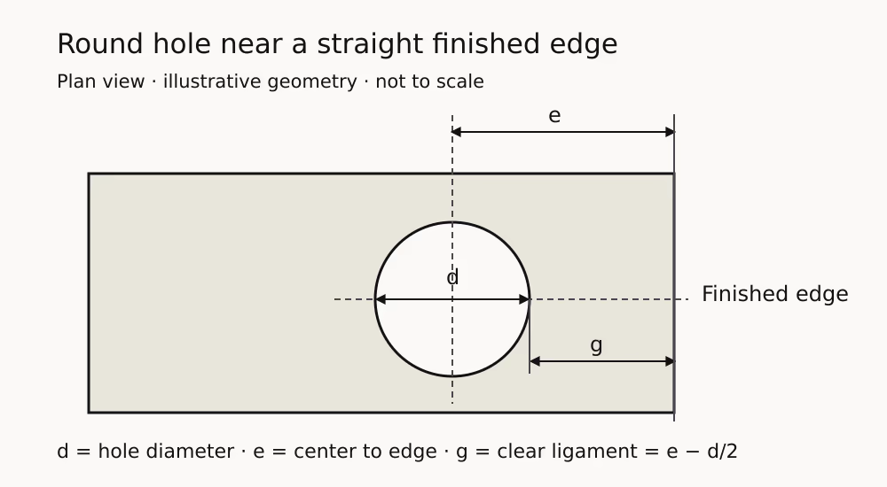
For example, take a nominal center-to-edge distance of 3.40 mm and a nominal finished hole diameter of 2.00 mm. The nominal ligament is 3.40 − 1.00 = 2.40 mm. However, if the center can approach the edge while the hole grows, the finished ligament gets smaller.
| Input or result | Nominal | Low-ligament screening case |
|---|---|---|
| Center to finished edge e | 3.40 mm | 3.25 mm, from 3.40 ± 0.15 mm |
| Finished hole diameter d | 2.00 mm | 2.10 mm, from 2.00 ± 0.10 mm |
| Clear ligament e − d/2 | 2.40 mm | 2.20 mm |
| Stock used in spacing ratio | 1.50 mm | 1.55 mm |
| Clear ligament / stock | 1.60 | 1.42 |
Here, the low-ligament case is 3.25 − 2.10/2 = 2.20 mm. Using maximum stock gives 2.20 ÷ 1.55 ≈ 1.42. Here, the example assumes the tolerances can act together. When location and profile are controlled separately, use their actual datum references and allowed boundary movement.
Mate’s published hole-to-sheet-edge screen is 2 times stock thickness. At 1.55 mm, that reference corresponds to 3.10 mm of clear metal, so the example is 0.90 mm below it. Therefore, this difference is a prompt for tooling review. However, the published figure is supplier guidance, and the project die may have different support and sequencing.
For comparison, moving the nominal center 0.90 mm away from the edge would yield a calculated 3.10 mm worst-case ligament with the same assumed allowances. Reducing the hole diameter by 0.20 mm would add only 0.10 mm of ligament and would make the minimum hole size review more demanding. Check assembly access and fit before choosing either change.
Similarly, for two circular openings, subtract both radii from the center spacing to get the clear web. For a curved edge or irregular cutout, check the nearest points of the toleranced profiles. Separately, if a bend is nearby, use the specified bend reference. Dayton Rogers’ punched-hole design guidance discusses bend proximity, inspection in the burnished land or on the punch side, and piercing after forming as an option when geometry warrants it.
In practice, moving a hole can improve edge spacing without reducing the diameter toward the minimum hole size. However, the new location still has to satisfy the mating layout. Overlay the proposed position on the mating drawing before issuing a revision.
Review tooling and approve the finished feature
First, mark which requirements come from assembly or function. Give the die builder the finished drawing, material callout and relevant mating part information. For pierced holes that locate a pin, for instance, agree on the functional datum and how the pin engages the finished part.
Next, request a drawing review through SSP’s stamping die development and tryout service when the design approaches the proposed process limit. Identify the planned piercing station, how the sheet is supported and which operation creates the neighboring finished edge. Then choose evidence that can distinguish a cutting issue from distortion introduced at a later station.
For example, if the tool pierces before an adjacent bend, request sample measurements at both stages where practical. Then measure size and location using the agreed references. Also, check the ligament on finished parts and record any distortion or burr that matters to seating, handling or clearance. If the feature is close to a formed edge, request a clear definition of where the measurement is taken.
Likewise, when comparing physical stamping die configurations, ask each supplier to identify the punch and guidance assumed in its minimum hole size proposal. By contrast, a quote that lists only a hole diameter leaves the basis of comparison unclear. Include the proposed replacement punch and the method for checking the first accepted samples.
Finally, record disposition against each requirement. Where a screening value is missed, assign a specific action: obtain tooling approval with relevant trials, move the feature, change the size with assembly approval, or evaluate a secondary operation. Ultimately, keep production acceptance tied to the finished drawing. For sourcing context, see SSP Precision’s tooling and manufacturing overview.
For inspection, keep the minimum hole size decision separate from the method for measuring the finished hole. Specify which face is inspected and how the gauge contacts the part. In particular, agree on how to handle readings that vary through the cut profile.
If a trial misses the requirement, retain the raw measurements and stage of manufacture. For instance, a part can meet minimum hole size at the piercing station and fail a functional gauge after forming. A before-and-after check gives the team a way to isolate where the change occurred.
Finally, include the approved minimum hole size in the controlled review record, with the drawing revision and related measurement plan. That gives procurement and quality a shared basis for reassessing future drawing or supplier changes.
Key takeaways
- Screen minimum hole size against the intended punch, stock and guidance.
- Calculate the clear ligament from the finished boundaries at their limiting dimensions.
- Document which ratios come from the supplier and which dimensions control part acceptance.
- Approve geometry near a process limit with a documented trial and a repeatable inspection method.
Frequently asked questions
Is minimum hole size always equal to the stock thickness?
No. A diameter equal to the stock thickness is one screening point. The appropriate starting value depends on the material and punch support. For instance, Mate lists different ratios for guided and non-guided stainless tooling. Confirm the actual die setup and verify the finished hole.
Is hole-to-edge clearance measured from the hole center?
For the screening method in this guide, measure from the hole boundary to the finished edge. For a round hole beside a straight edge, subtract half the hole diameter from the perpendicular distance between the center and the edge. For irregular profiles, check the nearest points on the toleranced boundaries.
Does passing the geometry screen approve the hole for production?
No. Instead, the screen identifies which risks to review. Approve the feature with relevant trial parts and evidence that the drawing, assembly and tool-maintenance requirements are met under the proposed production setup.