






EMI enclosure seams need a defined contact interface, a controlled closure gap and validation of the assembled product. Review the removable cover as an electrical and mechanical interface. A nominal gasket squeeze or a continuity reading alone should not become the acceptance certificate for the complete enclosure.
This application guide helps OEM mechanical, tooling and quality engineers specify EMI enclosure seams before releasing a stamped cover. It develops a reproducible compression example and an approval worksheet, while keeping shielding performance separate from dimensional conformity.
Define EMI enclosure seams around the removable cover
First, identify the EMI enclosure seams being approved: the lid perimeter, an access panel or another separable joint. Mark its complete path on the assembly drawing, including corners and interruptions. For EMI enclosure seams, this path is the interface under review, rather than simply the outside silhouette of the enclosure.
Parker Chomerics explains that discontinuities can permit electromagnetic leakage and that a conductive gasket helps maintain current continuity across a joint. Its shielding theory also distinguishes leakage through gasket material from leakage at the interface. Therefore, review the contact surfaces as well as the gasket itself. Parker: shielding and gasket interface theory.
Next, ask the electrical engineer to identify the relevant operating states and the test requirement. Record whether the concern is emissions leaving the assembly, susceptibility to external fields, or both. Likewise, identify the frequency range and applicable assessment method before requesting a shielding figure from a supplier.
For the drawing review, assign identities to each seam segment. For example, call the straight side S1 and the neighboring corner C1, then use those identities in inspection records. This proposed naming method makes observations repeatable without implying that either location has already passed an RF test.
Also, mark cables, vents and connector openings as separate interfaces requiring review. The scope here is the removable stamped seam. Nevertheless, a validation record should state which surrounding features were present during testing so that a seam decision is not detached from the assembly in which it was evaluated.
For sourcing context, SSP Precision’s tooling and manufacturing overview introduces the company’s published offerings. Keep the technical request specific: a formed cover and interface drawing for review. Do not infer an EMC certification or an enclosure testing service from a general manufacturing description.
Review EMI gaskets with the stamped flange
First, request a named gasket construction and its supplier documentation. EMI gaskets should be evaluated with the proposed flange material, finish, available contact land and closure arrangement. TE Connectivity emphasizes the need to provide sufficient seam land for the selected gasket. TE: mechanical design considerations for EMC shielding.
Next, make the interface definition explicit. Specify the substrate and finish on both sides, the contact-land boundaries and the treatment of adjacent paint. Parker’s engineering handbook addresses conductive mating surfaces, coating exclusion from contact regions, flange stiffness and the consequences of uneven closure. Use its guidance to frame a supplier review, rather than copying a generic finish recommendation onto an unrelated material combination. Parker: gasket design overview and engineering handbook.
For EMI enclosure seams, request written confirmation of compatibility between the gasket, substrate, finish and expected exposure. However, do not treat a material name as proof of environmental durability. The proposed approval record should identify the exposure conditions and the evidence the responsible engineer accepts.
Likewise, EMI gaskets need a documented installation method. Ask how corners, joints and replacement lengths will be handled. Record which surfaces may receive adhesive and which must form the intended electrical interface. Then have the gasket supplier review the EMI enclosure seams in the exact assembly, including any installation detail missing from the catalog sketch.
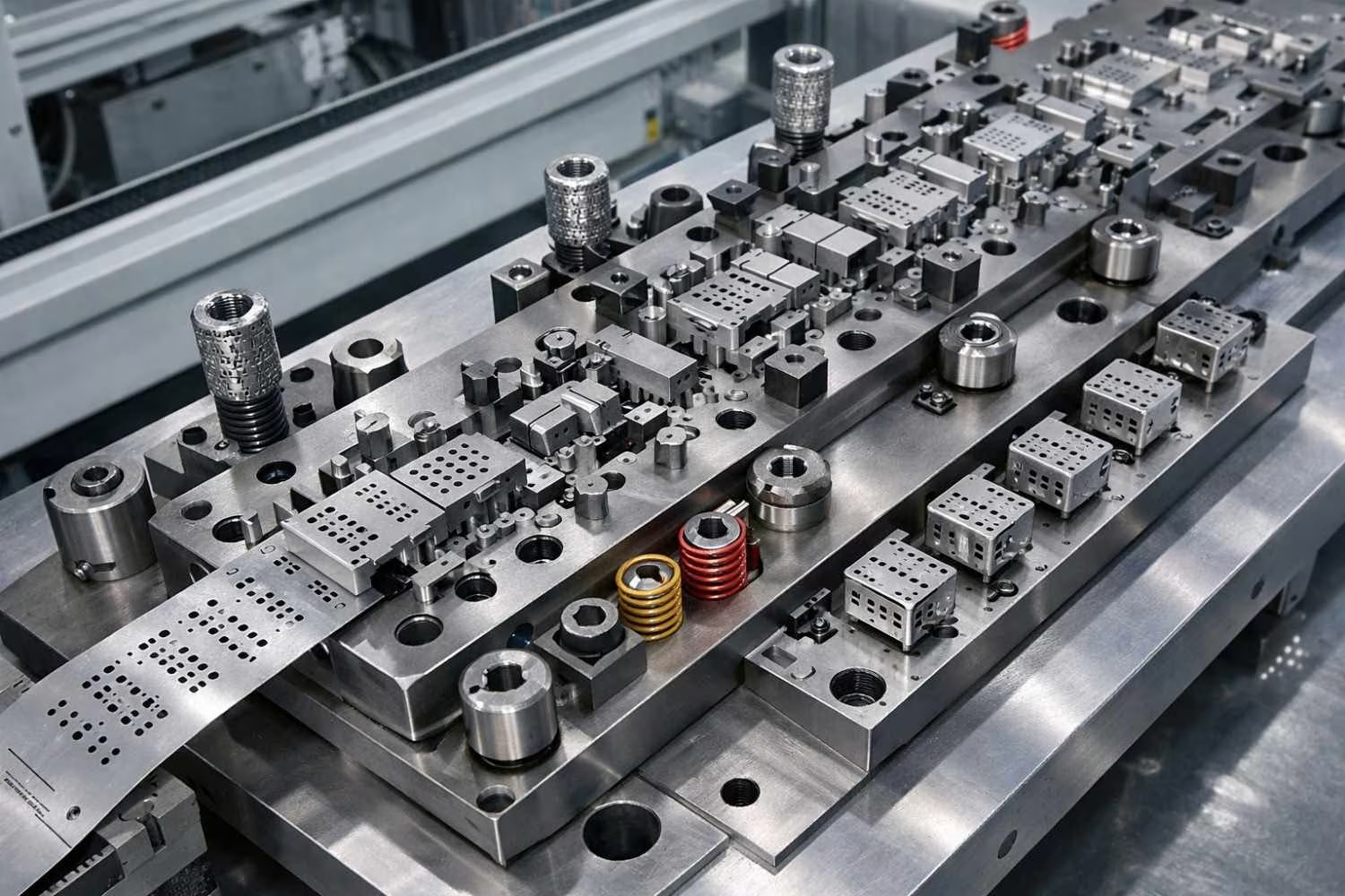
When comparing SSP’s physical stamping die configurations, explain which features create the cover flange and which surfaces locate the assembled lid. The die is the forming tool; the finished joint still needs its own approved drawing and validation evidence.
Keep contact resistance checks separate from RF approval
For inspection planning, define what a contact resistance reading represents: the two measurement locations, instrument setup, assembly state and acceptance criterion. For EMI enclosure seams, record the actual method beside the result. This is a proposed control practice, not a universal resistance threshold.
In particular, a contact resistance check should answer a limited interface question. It should not be converted into a shielding-effectiveness figure without a justified method. Parker’s theory distinguishes the material path from the interface path; accordingly, the approval plan for EMI enclosure seams assigns RF evidence to a separate evaluation of the assembled configuration.
For EMI enclosure seams that are periodically opened, propose a reassembly check with the responsible engineer. State the number of operations, replacement rules and observations required by the project. Do not invent a standard service-life cycle count or assume that the original closure condition persists after maintenance.
Calculate the local gasket compression extremes
For this example, let h be the free gasket height and g the local closed separation between its seating surfaces. Both dimensions are in millimeters. First, define the gasket compression tolerance budget from these two input ranges. Define calculated compression as C = 100 × (h − g) / h, expressed as a percentage of free height.
This equation is a geometric definition for the simplified example. It does not calculate closure force, conductive contact area, aging or shielding effectiveness. Therefore, use it as one input to stamped enclosure seam validation, with supplier approval still required for the actual gasket and installation.
Assume a hypothetical free height of 2.00 ± 0.05 mm and a local closed gap of 1.60 ± 0.15 mm. Here the gap tolerance is an assumed total local assembly allowance. It already represents the simplified combined variation, so do not add the same cover variation a second time.
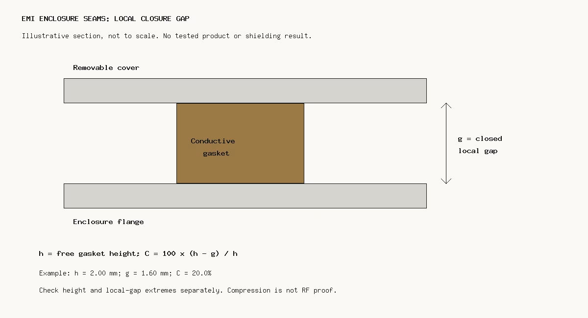
At nominal dimensions, C = 100 × (2.00 − 1.60) / 2.00 = 20.00%. However, EMI enclosure seams must also be reviewed at their limiting combinations. For EMI enclosure seams with positive gap and height, compression decreases as gap increases and increases as free height increases.
| Evaluation case | Free height h (mm) | Local gap g (mm) | h − g (mm) | Calculated C (%) |
|---|---|---|---|---|
| Nominal | 2.00 | 1.60 | 0.40 | 20.00 |
| Lowest compression | 1.95 | 1.75 | 0.20 | 10.26 |
| Highest compression | 2.05 | 1.45 | 0.60 | 29.27 |
| Sensitivity: raised local gap | 2.00 | 1.70 | 0.30 | 15.00 |
For example, the low extreme is 100 × 0.20 / 1.95 = 10.2564…%. Conversely, the high extreme is 100 × 0.60 / 2.05 = 29.2683…%. Values in the table are rounded to two decimal places only after calculation.
For sensitivity, raising the gap from 1.60 to 1.70 mm at a fixed 2.00 mm height lowers compression from 20% to 15%. That is a reduction of five percentage points. Thus, the nominal value alone conceals a decision-relevant range in this illustrative review of EMI enclosure seams.
Next, compare both extremes with the actual supplier’s permitted deflection and closure-force information for the selected profile and installation. Parker’s handbook discusses profile-dependent deflection and flange deformation. Accordingly, this guide deliberately does not assign the hypothetical result a universal pass or fail.
Also, evaluate the gap locally along the perimeter. A single nominal separation in CAD is insufficient evidence that each point on EMI enclosure seams has the same assembled condition. Propose measurement locations at straight sections, corners and between fasteners, then agree how the cover is supported and closed during inspection.
If the calculated range falls outside the supplier-approved window, investigate the assumptions before changing a part. For example, request a tighter gap budget, a different profile or a revised closure concept. Then repeat the calculation and obtain approval of the updated configuration; a numerical improvement alone is not a shielding test.
Build a separate evidence record for each approval decision
For EMI enclosure seams, organize release around three questions: does the geometry conform, is the interface assembled as specified, and does the evaluated assembly meet its electrical requirement? The following worksheet is a proposed engineering asset. It contains no measured results or mandatory industry limits.
| Decision | Evidence to request | Conditions to record | Decision boundary |
|---|---|---|---|
| Drawing conformity | Local gap and contact-land measurements | Datums, finish, support and closure state | Dimensions alone do not approve RF performance |
| Gasket suitability | Supplier approval of calculated extremes and closure requirements | Exact profile, material, height limits and installation | Catalog data need matching conditions |
| Interface consistency | Documented electrical contact check | Instrument method, probe locations and assembly revision | Do not substitute a DC result for RF evidence |
| Assembled RF performance | Test report against the project requirement | Frequency range, setup, cables, openings and operating state | Approval applies to the evaluated configuration |
| Service condition | Agreed reassembly and exposure evaluation | Opening cycles, gasket replacement and finish condition | Project-specific plan; no universal cycle count |
First, assign an owner to each row and keep unresolved items visible. For instance, dimensional approval may be complete while the supplier review remains open. Record that distinction instead of releasing EMI enclosure seams under one ambiguous “checked” status.
Next, include the approved interface requirements in the request for stamping die development and tryout. Ask the toolmaker how formed samples will be assessed against the functional datums. Keep tooling acceptance distinct from the system engineer’s final electrical approval.
For trial planning, propose measurements before and after assembly where accessible. Then compare any change against the defined closure state. This proposed sequence helps the team decide whether to investigate the formed part, the mating enclosure or the closure method, without claiming a cause from an isolated observation.
Likewise, give procurement a controlled package: drawing revision, material and finish requirements, gasket identity, supplier approval and the validation plan. For stamped enclosure seam validation, this package is more useful than an unsupported request for a generic attenuation value.
Finally, specify change-control triggers for EMI enclosure seams. For EMI enclosure seams, a revised coating, gasket profile, flange geometry or closure arrangement should prompt an engineering review of the affected evidence. Determine the retest scope from the change and project requirement, rather than assuming every earlier approval remains transferable.
Key takeaways
- Define EMI enclosure seams as complete interfaces with controlled surfaces and assembly conditions.
- Calculate local compression at the limiting height and gap combinations.
- Keep hypothetical geometric results separate from supplier limits and actual test data.
- Release drawing conformity, interface checks and assembled RF performance as separate decisions.
Frequently asked questions
How do height and gap tolerances affect compression?
Here, gasket compression tolerance describes the calculated variation caused by free-height and local-gap limits. The hypothetical extremes are 10.26% and 29.27%. However, those values are not permitted limits; the selected supplier must review the actual profile and installation.
Can a nominal compression value approve EMI enclosure seams?
No. Instead, compare the local limiting combinations with supplier-approved conditions, then complete the project’s assembly validation. The example gives 20% nominal compression, but dimensional variation changes that value substantially before any RF evaluation is considered.
Does this application guide describe a tested SSP enclosure?
No. It is an illustrative engineering guide with hypothetical inputs and proposed review practices. The tooling photograph is contextual, and the original diagram explains geometry. Neither image is evidence of a customer project, measured shielding performance or completed validation.