Good snap-fit design starts with strain, not with a favorite hook shape. Define the required deflection, calculate the peak strain at the beam root, estimate the assembly force with an appropriate material modulus and friction range, then verify the molded parts through repeated assembly and environmental testing. A snap that assembles once without breaking is not automatically durable, removable, or manufacturable.
Engineering answer in brief
- Use the selected resin grade’s permissible strain, not a generic plastic value.
- Increase effective beam length and reduce abrupt root stiffness before simply making the hook thinner.
- Separate beam deflection force from the user-facing mating force, which also depends on lead angle and friction.
- Design mold release with the snap geometry. A functional hook may create an undercut that needs a shutoff, lifter, slide, or geometry change.
- Validate assembly force, retention, permanent set, whitening or cracking, dimensional variation, temperature, conditioning, and required cycles on molded parts.
What a snap fit must do
A snap joint uses a protruding feature such as a hook, stud, or bead that deflects during assembly and then engages an undercut in the mating part. The separation behavior depends on the undercut geometry, so the same basic principle can produce a serviceable joint or a joint intended for one-time assembly. Covestro, Snap-Fit Joints for Plastic: A Design Guide, pp. 3-4.
The design has to satisfy several different requirements at once: sufficient elastic deflection during assembly, acceptable operator or automation force, retention after engagement, freedom from unacceptable permanent set, and compatibility with the molding tool. Covestro identifies mechanical load and assembly force as primary design factors, while Protolabs notes that snap features add stress and flex and can require shutoffs, side actions, or a redesign for clean mold release. Covestro snap-joint guide, pp. 3 and 7-16; Protolabs, injection molding design guide.
A useful requirement therefore does not say only “add four clips.” It states what the clips retain, the maximum assembly force, whether the joint is removable, the number of assembly cycles, the service temperature and environment, the allowable gap or rattle, and the inspection method.
Choose the snap-joint type from the load path
Covestro groups common snap joints into cantilever, U-shaped, torsion, and annular forms. Cantilever features carry the joining deflection mainly in bending; torsion designs obtain motion by twisting a bar; annular designs engage around a rotationally symmetric feature and create a multiaxial stress state. Covestro snap-joint guide, pp. 4-6.
BASF’s published snap-fit overview similarly identifies straight, U-shaped, and L-shaped cantilevers and notes that U- and L-shaped forms can provide effective length where packaging restricts a straight beam. BASF, “Improving Snapfit Design, Part 1,” hosted by UL Prospector.
| Concept | Primary deformation | Useful when | Main checks |
|---|---|---|---|
| Straight cantilever | Beam bending | A direct beam and hook fit the available envelope. | Root strain, length, thickness, hook deflection, release direction. |
| U- or L-shaped cantilever | Distributed beam bending | The layout needs more effective flex length than a straight arm permits. | Corner radii, local torsion, wall interaction, nonlinear deflection. |
| Torsion snap | Twist of a molded bar | A rocker or release tab can rotate around an integral torsion member. | Shear strain, bar diameter and length, molded-in stress, cycle life. |
| Annular snap | Circumferential and multiaxial deformation | Round caps, housings, or shafts need continuous engagement. | Diameter interference, wall stiffness, lead angle, ovalization, removal force. |
This is a concept comparison, not a material allowables table. Use the selected material supplier’s method for final dimensioning.
Calculate cantilever strain before assembly force
For a simple rectangular, constant-thickness cantilever with small deflection, a screening estimate for maximum root strain is:
ε = 1.5yh/L2
where ε is outer-fiber strain, y is required tip deflection, h is beam thickness, and L is free beam length.
This form is consistent with the conventional cantilever relationships summarized in Covestro’s guide. The guide also treats permissible deflection as a function of both geometry and material strain, and warns that high snap-fit loads can extend beyond the linear stress-strain range, where a strain-dependent secant modulus should replace a single elastic-modulus value. Covestro snap-joint guide, pp. 7-12.
Illustrative strain calculation
Consider a hypothetical cantilever with a 20 mm free length, 1.5 mm root thickness, 8 mm width, and 1.2 mm required tip deflection. These values are assumptions for demonstrating the calculation; they are not SSP test data or a recommended universal geometry.
ε = 1.5 × 1.2 mm × 1.5 mm / (20 mm)2
ε = 0.00675 = 0.675%
The calculation is a screening result. It must be compared with a project-approved permissible strain for the exact resin grade, temperature, conditioning, molding history, and cycle requirement. Covestro’s tables, for example, provide grade-family guide values and advise using lower values for frequent separation and rejoining; those values should not be copied to an unrelated polymer or supplier grade. Covestro snap-joint guide, pp. 10-12.
Why length usually helps more than a small thickness change
The strain equation contains L squared. Holding required deflection constant, increasing free length reduces calculated strain rapidly, while increasing thickness raises strain. A tapered arm can use material more efficiently by relating the section to the local bending moment. Covestro recommends tapering thickness or width toward the hook and reports that a design tapering to half-thickness can increase permissible deflection by more than 60% compared with a constant section in its method. Covestro snap-joint guide, pp. 7 and 11.
The beam root still needs a controlled transition. An abrupt corner concentrates strain, but a very large fillet can create a thick mass beside the nominal wall and introduce molding concerns. Covestro describes this as a compromise between reducing stress concentration and avoiding a locally thick section. Covestro snap-joint guide, p. 8.
Estimate deflection force and mating force separately
For the same simple rectangular cantilever, a screening form for beam deflection force is:
P = bh2Esε / 6L
where b is beam width, h is root thickness, Es is the secant modulus at the design strain, ε is root strain, and L is free length.
Covestro uses this force relationship in its worked cantilever example and specifies a strain-dependent secant modulus for the calculation. Covestro snap-joint guide, pp. 11-16.
Using the hypothetical geometry above and an assumed secant modulus of 1,800 N/mm2, the estimated beam force is 1.82 N. The modulus is deliberately labeled an assumption; a real design must use data for the selected grade at the relevant strain and condition.
Lead angle and friction change what the assembler feels
The mating part does not usually push directly normal to the beam. It moves along a ramp, so the required mating force includes both the beam force and friction. Covestro gives the following relationship:
W = P(μ + tan α) / (1 – μ tan α)
where W is mating force, P is beam deflection force, μ is the friction coefficient, and α is the lead angle.
The same guide cautions that friction changes with relative speed, pressure, surface quality, and the material pairing. Treat a friction value as an input with uncertainty, not a universal constant. Covestro snap-joint guide, pp. 13-15.
| Assumed friction coefficient | Calculated mating force | Interpretation |
|---|---|---|
| 0.20 | 1.60 N | Low-friction screening case. |
| 0.30 | 1.93 N | Middle sensitivity case. |
| 0.50 | 2.76 N | Higher-friction screening case. |
These are arithmetic results from hypothetical inputs, not measured assembly forces. The example shows why surface condition and material pairing can change feel even when beam geometry is unchanged.
Material selection, fatigue, and stress relaxation
Material selection has to consider more than room-temperature tensile strength. Protolabs notes that a flexible resin may suit a snap feature while a stiff or brittle material may crack, and Covestro bases snap dimensioning on permissible strain rather than on stiffness alone. Protolabs injection molding guide; Covestro snap-joint guide, pp. 7-12.
Repeated assembly is a fatigue problem, not simply a repetition of the first event. Celanese states that polymer fatigue depends strongly on geometry, processing, temperature, environment, and load waveform, and that laboratory fatigue curves should be treated as starting points because end-use loading and self-heating can differ from the test. Celanese, Polyester Technical Manual, fatigue section.
A snap should ideally relax to a low-stress or stress-free state after engagement. If the beam remains deflected to supply continuous clamp load, time-dependent behavior becomes important. Celanese explains that creep is increasing strain under sustained stress, while stress relaxation is the decay of stress under sustained strain. Celanese polyester manual, creep and relaxation sections.
| Question | Required evidence | Why it matters |
|---|---|---|
| How much strain is permissible? | Grade-specific stress-strain data and supplier guidance at relevant temperature and conditioning. | Controls deflection without crack, yield, or unacceptable set. |
| What modulus belongs in the force model? | Secant or appropriate strain-dependent modulus for the design point. | Assembly-force prediction changes with stiffness at actual strain. |
| Will it be opened repeatedly? | Cycle target, load history, environmental state, and molded-part fatigue test. | One successful assembly does not establish cycle life. |
| Does it stay deflected? | Creep or relaxation data and retained-force testing. | Retention or sealing load can decay with time. |
| What changes in production? | Resin lot, colorant, regrind policy, moisture control, cavity, dimensions, and process records. | Material and molded geometry determine the actual strain distribution. |

Design the snap and the injection mold together
A hook that works mechanically can still trap the molded part. Protolabs explains that snap-feature undercuts may require a pickout, lifter, or other mechanism, while an intentional pass-through core and shutoff can sometimes form the hook without a side action. The available solution depends on geometry and tool constraints. Protolabs, “How to Incorporate Shut-Offs in Injection Molding Design”.
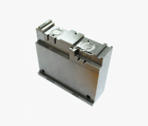
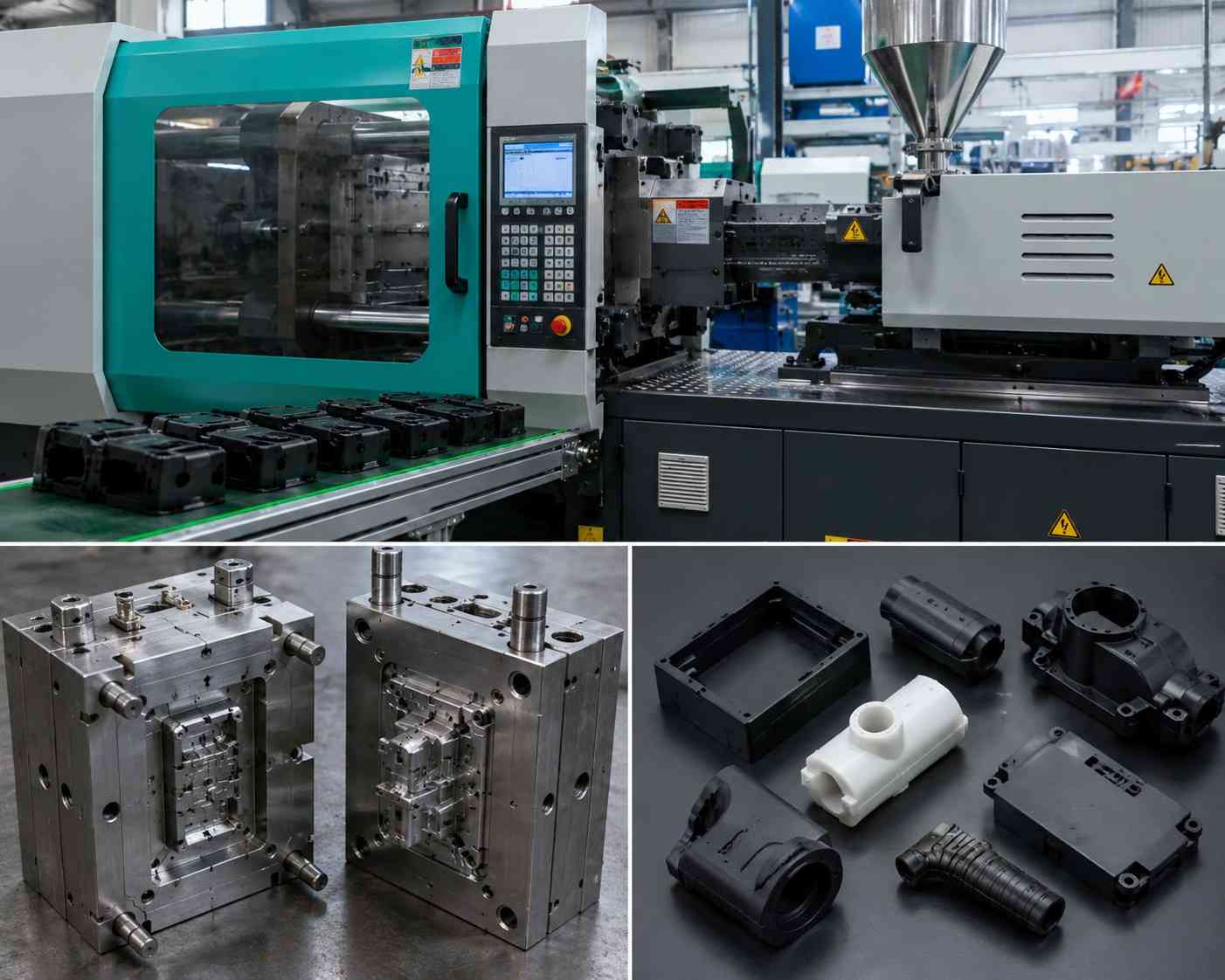
Review the beam’s draw direction, hook undercut, shutoff faces, draft, ejector contact, and room for steel before freezing the latch. The injection mold tooling configuration controls how the feature is formed and released, while the injection molding production process controls the material and dimensional state in which the snap is tested. Keeping those decisions separate prevents a good beam calculation from concealing a difficult or fragile tool condition.
Gate position and flow can also matter because the snap root is usually the highly strained section. The design review should therefore identify potential weld or knit lines, fiber orientation, air traps, and local packing variation around the root, then confirm their effect on molded samples. This is an engineering verification step, not a claim that a particular gate location always solves snap failures.
Validate force, retention, and required life on molded parts
Analytical equations are most useful for eliminating weak concepts and selecting a prototype range. They do not include every short-beam, large-deflection, root-geometry, anisotropy, friction, or tolerance effect. Covestro’s guide provides separate treatment for curved cross sections and for cases where both mating parts deform, illustrating why the simplest cantilever model has boundaries. Covestro snap-joint guide, pp. 9 and 24.
- Freeze the requirement. Record assembly-force limits, retention load, allowable gap, service conditions, removability, and cycle target.
- Freeze the specimen. Record resin grade, conditioning, colorant, regrind policy, molding cavity, dimensions, and process lot.
- Measure the geometry. Inspect free length, thickness, width, root radius, hook depth, lead and return angles, and mating-part location.
- Measure the event. Capture force versus displacement during assembly and removal. Record first engagement, peak force, seating, retention, and any stick-slip behavior.
- Inspect damage. Check root whitening, cracks, gouging, permanent set, incomplete seating, and mating-surface wear after defined intervals.
- Challenge the environment. Repeat the test after project-relevant temperature, humidity, chemical, UV, aging, or vibration exposure.
- Test process limits. Include parts molded at approved window limits and from relevant cavities, not only hand-selected nominal samples.
Set the sample quantity and statistical acceptance rule from the product risk and quality plan. A small engineering screen can expose obvious geometry problems, but it does not automatically establish production capability or life.
Snap-fit design release checklist
| Decision | Release evidence |
|---|---|
| Function | Defined assembly, retention, removal, gap, rattle, sealing, and cycle requirements. |
| Geometry | Strain calculation with measured L, h, y and root geometry; tolerance extremes checked. |
| Material | Exact grade and condition with permissible strain and appropriate modulus evidence. |
| Force | Calculated sensitivity to friction and angle plus measured force-displacement data. |
| Durability | Cycle, aging, fatigue, creep or relaxation testing matched to the actual use case. |
| Tooling | Approved draw direction, shutoff or action, draft, steel condition, venting, and ejection. |
| Process | Approved molding window and traceable cavity, lot, and conditioning records. |
| Inspection | Dimensional method and visual criteria for cracks, whitening, set, wear, and incomplete seating. |
Frequently asked questions
What is the basic snap-fit design equation?
For a simple rectangular constant-thickness cantilever, a useful screening equation is ε = 1.5yh/L2. It relates root strain to tip deflection, beam thickness, and free length. Use a supplier method for tapered, curved, short, or large-deflection beams and verify molded parts. Covestro snap-joint guide, pp. 7-12.
How can I reduce strain without losing the undercut?
Increase effective beam length, use a suitable taper, distribute deflection between mating parts where appropriate, or change the joint concept. Reducing thickness can lower stiffness but also changes force, tolerances, filling, and durability, so it should not be the only adjustment. Covestro documents the strain-distribution benefit of tapered beams. Covestro snap-joint guide, pp. 2 and 7-12.
Why is measured assembly force higher than the beam calculation?
The assembler must overcome ramp geometry and friction as well as beam deflection. Misalignment, part interference, texture, surface condition, rate, dimensional variation, and deformation of both parts can add further differences. Covestro separates deflection force from mating force and includes lead angle and friction in the latter. Covestro snap-joint guide, pp. 13-15.
Can a snap fit be opened repeatedly?
It can be designed for repeated service, but the required cycle count, material, strain, return angle, wear, environment, and residual deformation must be validated. Covestro recommends reduced permissible-strain guide values for frequent separation, and Celanese notes that plastic fatigue depends on geometry, process, temperature, environment, and load history. Covestro snap-joint guide, p. 12; Celanese polyester manual, fatigue section.
Do snap hooks always require a side action?
No. Some can be formed with pass-through cores and drafted shutoffs, while others require a lifter, slide, pickout, flexible release, or geometry change. The decision depends on the undercut, resin, surrounding geometry, release direction, and mold design. Protolabs shutoff design guidance.
References
- Covestro, Snap-Fit Joints for Plastic: A Design Guide.
- BASF, “Improving Snapfit Design, Part 1,” UL Prospector.
- Celanese, Polyester Technical Manual.
- Protolabs, Injection Molding Guide.
- Protolabs, How to Incorporate Shut-Offs in Injection Molding Design.