







Start sheet metal hemming design with the edge function, the permitted cross-section and the assembly envelope. Compare an open return, a flattened return and a teardrop profile against the actual material and forming proposal. Then define the dimensions and evidence needed to approve the finished edge.
This technical guide proposes an engineering review method. Its dimensional example uses hypothetical inputs and a simplified parallel-wall model, not SSP trial data or a universal forming rule. The original diagrams explain concepts; they do not establish an approved radius, tooling capacity or safe-touch classification.
For an OEM drawing review, the useful question is how to specify a sheet metal hem so the supplier can assess the edge and the inspector can reproduce its acceptance check. Agree the intended section before treating a process label as a complete manufacturing instruction.
Sheet metal hemming design begins with the edge function
First, identify what the folded edge must do. Possible design questions include covering a cut edge, providing a return for assembly or controlling the local section at a panel boundary. State the requirement and the affected surface rather than writing ‘hem all edges’ without a defined purpose.
For terminology, 247TailorSteel describes hemming as folding metal onto itself and distinguishes flat, open and teardrop forms. Its manufacturing restrictions apply to its own service. A profile shown in an educational guide is not proof that every supplier accepts it.
Next, show the neighboring component and its insertion or service path. In sheet metal hemming design, the final folded section and the space needed to assemble the part are separate review items. Ask the product team which clearance, contact or appearance requirement controls the choice.
Then identify the edge length and its start and end conditions. Mark nearby corners, cutouts, fasteners and locating features. For sheet metal hemming design, retain these relationships on an annotated model so a local edge detail does not conceal an interference elsewhere on the panel.
Before freezing the profile in sheet metal hemming design, decide whether the returned edge may contact the base sheet or must retain a specified opening. Include the actual measurement location in the decision. A gap requirement at the free end and an overall height requirement around the fold answer different questions.
Additionally, distinguish a single-sheet folded edge from an assembly that captures another sheet. If the edge joins components, define the complete material stack and required joint validation. This guide reviews the single-sheet section and does not establish joint strength, sealing performance or a joining-process qualification.
Compare hem types using a drawn section
First, place the candidate hem types beside the same functional requirement. A descriptive name is useful for discussion, but a dimensioned cross-section makes the requested result reviewable. State what the return looks like and where its controlled surfaces begin and end.
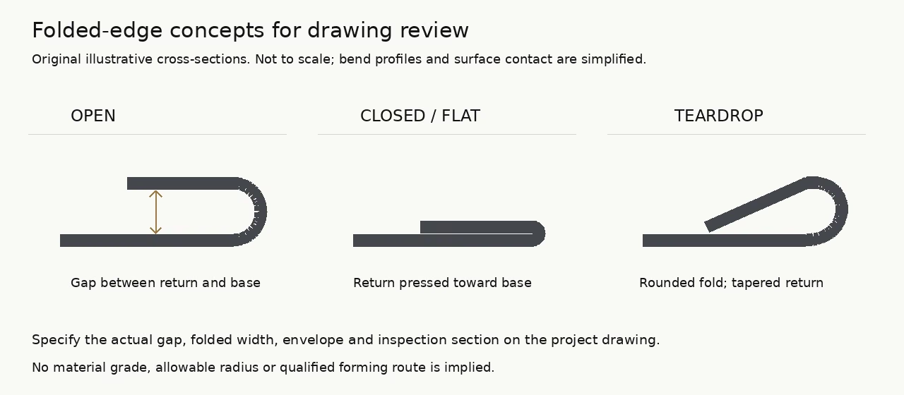
For an open return, define the clear opening between the faces and the extent over which it is controlled. For a teardrop proposal, show the rounded fold and the taper toward the returned edge. In sheet metal hemming design, an unlabeled circle or sketch without the mating part is insufficient to approve either concept.
Define what a closed hem must achieve
For a closed hem, identify the intended contact condition and the finished section envelope. Do not replace that description with a demand for an unspecified crushing force. The product drawing should define the accepted part, while the process team establishes a suitable forming method.
Next, compare the hem types in the worksheet below. The descriptions follow the named forms in the cited manufacturer guide; the review questions are proposed engineering checks. They are not a ranking of universal strength, cost or crack resistance.
| Concept | Section to show | Drawing decision | Evidence to request |
|---|---|---|---|
| Open return | Folded return with a gap | Opening, controlled length and entry clearance | Section measurement and assembly-access check |
| Closed / flat return | Return pressed toward the base | Contact condition and finished envelope | Profile and surface-condition inspection |
| Teardrop return | Rounded fold with a tapered return | Actual contour and adjacent-part clearance | Agreed section comparison and forming trial evidence |
Then review each proposal with the intended material and toolmaker. A closed hem is one candidate, not the default answer to every edge requirement. If a quotation changes the section to suit a supplier’s process, return that change to the design authority before approving the order.
For sheet metal hemming design, preserve the approved section in both the drawing package and the enquiry. Confirm that the model, drawing and supplier’s interpretation refer to the same revision. An accepted quotation for a process name should not silently supersede the requested geometry.
Review material, coating and the forming sequence
First, record the exact material grade, condition, nominal thickness and permitted thickness variation. Include any coating and the face on which appearance matters. In sheet metal hemming design, this material record belongs with the section proposal, not only in a general purchasing specification.
As a material reference, SSAB explains the role of ductility and material-specific bending guidance. It cautions that using a smaller punch radius than its recommendation increases cracking risk. Its grade-specific bending guidance should not be converted into a universal hem radius.
Next, obtain a review of the hemming bend radius for the actual material and process. Separate the radius formed on the part from the tooling dimensions used to produce it. Record the basis for any proposed value and the evidence needed before releasing a difficult or unproven combination.
For sheet metal hemming design, ask which observations will establish acceptable forming: the relevant section, the outer fold surface, the returned cut edge and the specified appearance face. Propose checking coating condition where the project requires it. Do not invent an allowable crack size or coating-damage threshold.
Then request the proposed operation sequence and handling orientation. TRUMPF describes a press-brake pre-bend followed by closing, and distinguishes a remaining gap from fully pressed-together sides. This is process context; it does not establish SSP equipment or prescribe a press-brake route for a stamped component.
Before accepting that sequence for sheet metal hemming design, ask how the workpiece is located and supported at each operation. Show the space needed for tool entry, closure and part removal. Keep the final-part envelope separate from the temporary shape and access needed during forming.
If adjacent features affect sheet metal hemming design, review them in the proposed order. Ask whether the earlier feature restricts access to the edge and whether the later operation requires a different locating condition. Treat any proposed change to the sequence as a review item with its own affected dimensions.
Additionally, define the inspection condition for sheet metal hemming design. Recommend recording whether the edge is free of external restraint or seated in a named fixture. A dimensional result should identify its support condition so the customer and supplier can compare the same geometry.
Check the local envelope before accepting the return
First, choose the section where the returned and base portions can be approximated as parallel walls. For this simplified sheet metal hemming design example, let t be the thickness of each wall and g the clear gap between them. The outside stack height at that location is E = 2t + g.
This is a geometric sum of two equal wall thicknesses and the intervening opening. It applies only at the selected parallel-wall section. It excludes the rounded nose, local deformation, unequal wall thickness, coatings and any nonparallel return. Check those parts of the real profile separately.
For hypothetical inputs, assume t = 0.80 ± 0.04 mm and g = 0.40 ± 0.10 mm. Also assume the local assembly allows 2.10 mm. These are teaching values, not material specifications, supplier tolerances or an approved opening for a particular sheet grade.
Then calculate the nominal section: E = 2 × 0.80 + 0.40 = 2.00 mm. The lower arithmetic extreme is 2 × 0.76 + 0.30 = 1.82 mm. The upper arithmetic extreme is 2 × 0.84 + 0.50 = 2.18 mm.
| Condition | Wall thickness t | Clear gap g | Calculated E = 2t + g | Clearance to assumed 2.10 allowance |
|---|---|---|---|---|
| Lower arithmetic extreme | 0.76 | 0.30 | 1.82 | +0.28 |
| Nominal | 0.80 | 0.40 | 2.00 | +0.10 |
| Upper arithmetic extreme | 0.84 | 0.50 | 2.18 | −0.08 |
Consequently, the nominal result fits the assumed local allowance, but the upper arithmetic extreme exceeds it by 0.08 mm. This identifies a drawing-review issue in the simplified model. It is not a prediction of a production distribution, process capability or the force needed to close the edge.
For sensitivity, increasing either assumed wall thickness by 0.01 mm on both layers increases E by 0.02 mm. Increasing g alone by 0.01 mm increases E by 0.01 mm. In sheet metal hemming design, this helps identify which dimensions enter this particular stack; it does not rank the actual process variation.
Next, compare the calculated section with the complete assembly model for sheet metal hemming design. Check the fold nose, the edge end and the neighboring fastener or cover as separate locations. The simplified stack does not prove that the maximum height of a teardrop profile fits inside the same allowance.
Before changing the gap to solve an envelope problem in sheet metal hemming design, review the edge function and forming proposal again. An opening may be required for insertion or another assembly condition. A drawing change must remain consistent with that requirement and with the material review.
Create a drawing and inspection approval record
First, make the sheet metal hemming design review reproducible. Retain the finished section, controlled edge length, gap or contact condition, outside envelope and nearby interfaces. State where each dimension applies and which datum or local reference the inspector should use.
When documenting how to specify a sheet metal hem, add the material record, surface requirements and agreed inspection condition to the same release package. Attach the supplier’s feasibility response. List unresolved questions explicitly instead of treating a preliminary sketch as a qualified production instruction.
Then build a practical inspection worksheet for sheet metal hemming design with fields for part revision, material identity, sample identity, section location, measured profile and disposition. Include the outer fold surface and edge-end observations required by the drawing. Record which checks are dimensional and which require an assembly or application assessment.
For sheet metal hemming design, agree the sampling and trial plan with the responsible quality engineer. Identify which material and tooling conditions the samples represent. This guide does not establish a universal sample count or claim that a satisfactory first article proves ongoing capability.
Next, preserve the relationship between the formed part and its approved blank-development basis. The existing bend-allowance and K-factor guide covers simple-bend calculations. Its cylindrical-bend example should not be treated as validation of a flattened or complex folded edge.
If a change is needed after tryout, identify whether it affects the blank, forming sequence, tooling or accepted part geometry. In sheet metal hemming design, update the responsible record rather than using an undocumented setup correction to hide a drawing conflict. Repeat the checks affected by the change.
Finally, discuss the physical tool proposal through SSP’s stamping-die product information and the review scope through its stamping-die manufacturing service. For an enquiry to SSP Precision, provide the edge section, material and acceptance requirements.
Key takeaways
- Tie sheet metal hemming design to the actual edge function and drawn cross-section.
- Specify the material, gap or contact condition, envelope and inspection location together.
- Use hypothetical stack calculations to expose questions, then verify the complete profile and forming proposal.
- Release the drawing, trial evidence and change record as a consistent package.
Frequently asked questions
Can one hemming bend radius be used for every material?
No universal radius is established here. Obtain the applicable material guidance and toolmaker review for the grade, condition, thickness and proposed sequence. Keep the part radius, tooling dimensions and acceptance evidence separately identified.
Does the parallel-wall stack give the complete hem height?
It gives only the outside height at the selected idealized section. Review the fold nose, nonparallel portions, coatings and local dimensional changes separately. The worked inputs are hypothetical and do not qualify an actual part.
What should a purchase drawing say beyond the word hem?
Show the intended section, affected edge length, material, gap or contact condition, outside envelope and inspection references. Record the supplier’s accepted interpretation and retain the evidence that supports the final release.