








Use an SPI surface finish chart to identify a mold-finishing preparation, then approve the required result on the intended molded part. Record the grade, affected faces, exact resin and color, reference sample and inspection method. Manufacturer charts associate SPI grades with diamond, paper, stone and blast preparations, but their published roughness ranges are not always the same. [1] DME; [2] Protolabs Network.
This guide explains the twelve familiar grades, shows a checked unit conversion and compares conflicting supplier roughness values. It then turns the selection into a drawing and sample-approval plan. The objective is a finish that meets the product’s appearance and functional requirements, rather than a polished surface specified everywhere without a reason.
Finish selection in brief
- Specify the surface and purpose before selecting a finish code.
- Identify the chart or physical comparator used to interpret the grade.
- Keep microinches, micrometers, Ra and Sa distinct.
- Evaluate the intended resin, color and filler combination on representative samples.
- Separate cosmetic approval, measured texture and functional performance.
SPI surface finish chart: identify the preparation first
DME’s Micro-Finish guide groups the grades below by preparation. Read this table as a manufacturer preparation reference, not a reproduction of a complete normative specification or a guarantee of the molded component’s gloss. [1] DME. Use the finish code alongside the identified comparator or approved project procedure when requesting a quotation.
| SPI designation | Preparation reference | Preparation family |
|---|---|---|
| A-1 | Diamond buff, grade #3 | Diamond |
| A-2 | Diamond buff, grade #6 | Diamond |
| A-3 | Diamond buff, grade #15 | Diamond |
| B-1 | Abrasive paper, 600 grit | Paper |
| B-2 | Abrasive paper, 400 grit | Paper |
| B-3 | Abrasive paper, 320 grit | Paper |
| C-1 | Abrasive stone, 600 | Stone |
| C-2 | Abrasive stone, 400 | Stone |
| C-3 | Abrasive stone, 320 | Stone |
| D-1 | Glass-bead dry blast, #11 | Dry blast |
| D-2 | Oxide dry blast, #240 | Dry blast |
| D-3 | Oxide dry blast, #24 | Dry blast |
Specify SPI polish grades on the drawing
Keep the prefix and numeral of the SPI polish grades together in the drawing note. Do not use “finish 1” without identifying the system, or shorten a requirement to “polish” when different faces need different treatments. Also distinguish a finish designation from a mold-base brand or a mold construction classification. Those decisions address different purchasing questions.
Source wording can differ even for preparation descriptions. DME lists A-2 with grade #6 diamond buff, while Protolabs’ surface-finish page describes its SPI-A2 option as grade #2 diamond buff. [1] DME; [3] Protolabs. Rather than silently making those descriptions identical, ask the supplier which physical reference and finishing procedure its quotation uses.
Do not translate a proprietary texture into an SPI grade merely because the photographs look similar. Protolabs distinguishes its PM finish options from SPI callouts and separately discusses Mold-Tech textures produced by chemical or laser processes. [4] Protolabs. Preserve the original texture identifier and supplier reference when that is what the product designer actually selected.
Read published Ra ranges with their source and units
Roughness comparison tables are useful for orientation, but they require a source check before becoming acceptance limits. Table 2 deliberately retains two suppliers’ published values. The DME figures are labeled approximate resulting Ra in microinches; Protolabs Network reports typical Ra in micrometers. [1] DME; [2] Protolabs Network.
NIST gives the international inch as exactly 25.4 mm. Therefore one microinch, written µin, equals 0.0254 µm. Convert a microinch value by multiplying it by 0.0254; do not substitute millimeters or divide a micrometer value by the same factor in the wrong direction. [5] NIST. The converted endpoints below are arithmetic results, not new measurements.
| SPI grade | DME approximate Ra (µin) [1] | DME range converted to µm | Protolabs Network typical Ra (µm) [2] |
|---|---|---|---|
| C-1 | 10–12 | 0.2540–0.3048 | 0.35–0.40 |
| D-1 | 10–12 | 0.2540–0.3048 | 0.80–1.00 |
| D-3 | 190–230 | 4.8260–5.8420 | 3.20–18.0 |
DME’s blast values accompany stated preparation conditions: D-1 uses an 8-inch distance, 100 psi and 5 seconds; D-3 uses a 6-inch distance, 100 psi and 5 seconds. [1] DME. These are context for its guide, not recommended operating instructions for an SSP tool or a substitute for a finishing supplier’s process.
For C-1, the calculation is 10 × 0.0254 = 0.2540 µm and 12 × 0.0254 = 0.3048 µm. For D-3, 190 × 0.0254 = 4.8260 µm and 230 × 0.0254 = 5.8420 µm. Extra decimal places preserve the conversion arithmetic; they do not imply that the approximate source range has gained measurement accuracy.
The comparison establishes a practical limit to chart-only purchasing: converting units does not make these published ranges identical. Do not average the sources, widen a tolerance to cover every website or select the most convenient endpoint. If roughness matters to acceptance, agree the required parameter, surface, method and limit explicitly, with a named reference for the finish.
Separate roughness, visual appearance and functional performance
KEYENCE defines Ra as the average absolute height deviation of a profile from its mean line. It distinguishes that line-based parameter from Sa, which averages deviations over an area. Sampling, filtering and trace direction can affect the reported result, and there is no universal factor that converts an Ra requirement into Sa. [6] KEYENCE.
That distinction belongs in the inspection plan. Identify whether the requirement concerns mold steel or the molded plastic, which area is measured, which parameter applies, and the measurement procedure to use. A report for a convenient flat patch should not silently replace the agreed check on the critical surface.
KEYENCE also explains that equal Ra values can describe surfaces with different profile characteristics. [6] KEYENCE. Consequently, treat a satisfactory average as evidence for the specified parameter, not automatic proof of acceptable appearance or sealing, friction or optical function. Decide which additional observations or application tests answer the actual product question.
For example, recommend separate approval records for the visible outer face and a functional contact band. The outer face may require comparison to an agreed appearance sample. The contact band may require a defined texture measurement and a functional check. Keep both decisions attached to their own surface identities, rather than assuming one finish code closes every requirement.
When a laboratory proposes an areal measurement in place of a profile requirement, request a documented correlation and approval of the revised criterion. Do not relabel an Sa result as Ra. Preserve the instrument method and settings needed to compare later reports, without claiming that a particular instrument or inspection capability is available at SSP.
Review injection mold surface finish with the intended resin
Protolabs notes that hardness, color and fillers affect how a molded surface presents a texture. It cautions that glass or mineral filling can complicate cosmetic appearance and recommends obtaining a plaque in the intended material. [3] Protolabs. Treat a generic resin-family recommendation as a starting point for review, not approval of every commercial grade and color.
The injection mold surface finish review should record the complete material designation, filler content where applicable, color reference and any permitted substitution. If a purchasing change alters one of those inputs, reopen the appearance decision. Keep the supplier’s material documentation beside the approved sample so a visually different batch is investigated against known information.
Finish also has to be feasible on the actual mold geometry. Protolabs points out that some deep, thin features are difficult to reach for finishing and that textured faces can require additional draft review. [3] Protolabs. Identify those areas before treating the finish plan as an instruction ready for machining and polishing.
The separate draft-angle guide for textured and deep features covers release geometry. In this finish review, mark the withdrawal direction for each affected face and ask the toolmaker and finishing supplier to confirm access and release. Do not assign one draft angle to every SPI family or turn a proprietary texture rule into a universal requirement.
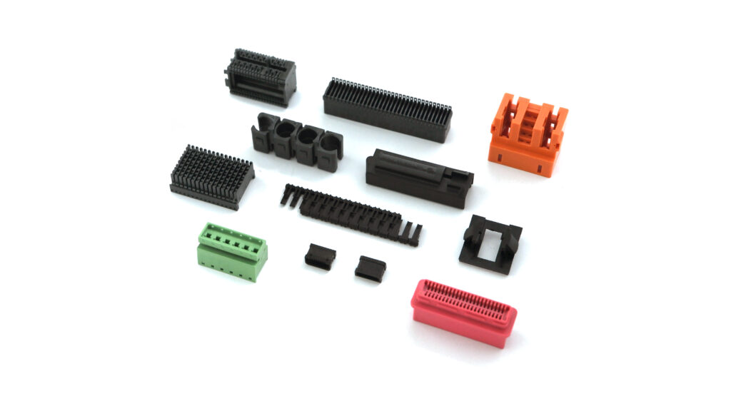
Specify finish zones rather than one instruction for the whole part
A useful drawing package maps the required finishes to named faces and states what happens at their boundaries. Protolabs describes masking areas that should not receive a texture and identifying the desired finish on the relevant surfaces. [4] Protolabs. Use those concepts to prepare an explicit project review, without assuming that every narrow feature can be masked or polished by the same method.
| Surface zone | Requirement to define | Evidence requested before approval |
|---|---|---|
| Visible outer face | Named finish reference, color, allowable witness and cosmetic boundary | Representative molded sample under agreed viewing conditions |
| Assembly contact or locating face | Functional dimensions and surface requirement for the actual interface | Dimensional and application-specific acceptance results |
| Sealing or sliding band | Texture parameter, measurement area and functional acceptance method | Relevant surface report and agreed component test |
| Hidden interior region | Required tool-mark removal, finish boundary and relevant release concerns | Toolmaker feasibility review and approved part condition |
| Texture transition or repaired area | Boundary location and appearance continuity to be accepted | Updated reference sample and change approval |
State whether gate, parting-line and ejector witness marks fall within the cosmetic acceptance decision or have separate requirements. Show excluded areas on the same drawing revision. A finishing instruction should not leave the supplier to guess whether a functional land is included in a cosmetic texture zone.
For the physical injection mold and cavity tooling, request the preparation reference, zone map and finishing-access review. For the injection molding production service, agree the resin, color, sample identification and finished-part acceptance records. These are connected decisions with different evidence.
Plan representative samples without confusing a trial with qualification
Hypothetical planning example: Suppose a product team wants to compare two resin grades, two colors and three candidate finishes. A complete combination matrix contains 2 × 2 × 3 = 12 conditions. If the team allocates four parts to each condition, the teaching allocation is 12 × 4 = 48 parts. No samples were produced for this guide.
This is an inventory calculation, not a statistically justified qualification plan or a standard sample quantity. Decide the actual replication, cavity coverage, process conditions and test allocation from the project risk and acceptance requirements. Identify destructive or functional tests separately so one sample is not allocated to incompatible uses.
Ask the moldmaker how the finish comparison can be represented physically, for example through a reviewed plaque or interchangeable-insert program. Do not assume the production cavity can provide every finish condition without a separate tooling plan. Record which geometry, texture boundaries and release surfaces the sample represents, and which questions remain for the real component.
For each condition, retain the material and color identities, finish reference, process record and sample designation. Review the same designated surfaces using an agreed presentation and inspection procedure. Keep appearance comments separate from the measurement results so a favorable impression cannot overwrite a failed numerical requirement.
If the sample does not reproduce the intended finish, investigate material, finishing reference, geometry and process evidence before upgrading the polish automatically. The proposed review should explain what changed and how the next trial will distinguish the competing explanations, rather than promising that a finer grade will fix every appearance issue.
Release the finish specification with its evidence and change controls
The approval record should identify the drawing revision, finish-zone map, reference samples, exact material and color, agreed measurements and any remaining exceptions. State who approves each decision. Retain the accepted and rejected sample identities where they help interpret the boundary, instead of relying on an undocumented verbal preference.
Reopen the relevant review after a finish change, material substitution, tooling repair or cosmetic-zone revision. Ask whether the original reference still applies and which evidence needs renewal. Avoid transferring an approval between different grades, resins or component geometries merely because the finish label looks familiar.
For a project discussion with SSP Precision, send the part drawing, exact resin and color, marked finish zones and the appearance or functional requirement. Request a quotation that identifies the intended finish reference and sample-approval scope. This gives the team a concrete basis for review without assuming an undocumented certification, roughness capability or cosmetic result.
Frequently asked questions
Does an SPI grade guarantee a particular molded-part Ra?
Do not treat a generic chart as that guarantee. The supplier ranges compared above differ, and molded appearance also depends on material. Agree the surface, parameter, method and acceptance limit for the actual project. [1] DME; [2] Protolabs Network.
How do I convert microinches to micrometers?
Multiply by 0.0254. The factor follows from NIST’s exact 25.4 mm international inch definition. For example, 12 µin converts to 0.3048 µm; conversion does not increase the precision of an approximate input. [5] NIST.
Can I replace an Ra limit with the same numerical Sa limit?
No direct substitution is established by the names. KEYENCE explains that profile and areal results use different sampling and filtering; a revised acceptance criterion needs validation on the relevant surface. [6] KEYENCE.
Should every textured wall use the same draft?
Review the selected texture, geometry and release direction with the supplier. Protolabs identifies finish access and draft as design concerns; its named process rules should not be generalized to every tool. [3] Protolabs.
Can a photograph approve the finish grade?
In this proposed workflow, use photographs to document the sample identity and observations. Keep the agreed physical reference and any required measurements or functional results as separate acceptance evidence. The contextual photographs in this article establish no finish grade.
References and interpretation limits
Sources were reviewed on 27 October 2026. The guide preserves source-specific preparation and roughness descriptions rather than presenting a harmonized universal roughness specification. Unit conversions are checked calculations. The finish-zone worksheet and sample allocation are original proposed planning material, not SSP project or test evidence.