






Start injection molding boss design with the selected screw, exact resin and assembly load. Specify the core geometry, wall section, engagement and head seating together. Then qualify the joint using measured assembly and failure behavior on representative molded parts.
For an OEM drawing review, the decision is which geometry can be molded, assembled and accepted with the chosen fastener. This guide explains how to design a plastic screw boss with a dimensional worksheet and a controlled assembly review. The numerical torque example is hypothetical.
Injection molding boss design begins with the joint inputs
First, name the fastener family and part number. A screw designed to form threads directly in thermoplastic brings its own geometry recommendations. Obtain those recommendations for the exact resin grade, filler content and expected installation cycles before freezing the molded screw boss.
For example, TR Fastenings’ Plas-Tech 30-20 guidance describes a thread that displaces plastic to form the mating internal thread. Its dimensions and joint behavior are associated with that fastener design. Use its values only within the supplier’s stated application guidance.
Next, document the mating part, head-bearing face and required clamp function. For injection molding boss design, sketch where the load enters the boss and how it travels into the housing. Identify whether the screw must retain a cover, locate a bracket or carry a repeated external force.
Then define the assembly stack and screw length for injection molding boss design. Show the clearance through the mating piece, the useful thread engagement and the space below the tip. Include tolerances in that stack so a long screw at one extreme cannot bottom before its head seats.
For the material record, retain the resin grade and condition used for assembly. Include the intended temperature, moisture condition and any chemical exposure in the review. The product team should decide which of these conditions requires a separate assembly or service test.
Before choosing a production driver setting, state the joint’s acceptance requirements. Define which evidence demonstrates seating and retention, what visible damage is unacceptable, and whether removal and reinstallation are required. For injection molding boss design, retain those criteria beside the geometry proposal.
Review the screw boss wall and its support
First, draw a section through the screw boss and the nearest wall. Compare the isolated, supported and wall-adjacent concepts below. The illustration supplies a review vocabulary for the load path. Each proposal still requires a dimensional and molding review.
For an isolated feature, ask how the boss base transfers the assembly load into the surrounding floor. For a supported feature, trace the load through the added rib. For a feature close to the sidewall, check the actual gap, local material buildup and tool access at the junction.
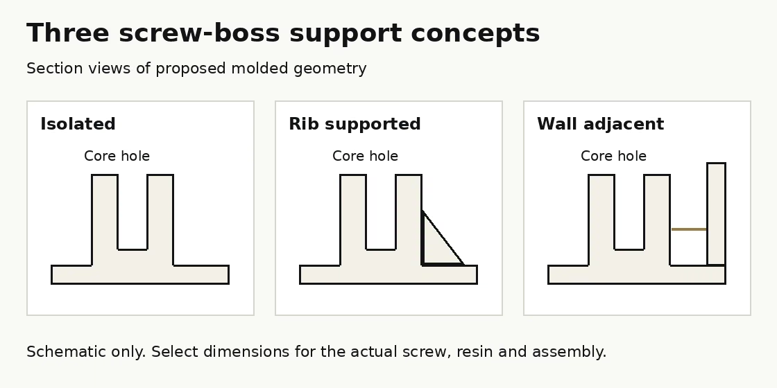
Then compare the local sections for moldability. Protolabs’ wall-thickness guide explains why uneven and thick regions can create molding difficulties. In injection molding boss design, examine the boss-to-floor and boss-to-rib intersections on the actual section before adding material to increase support.
If the outer face is cosmetic, include the opposite wall in the injection molding boss design sample approval. Keep the visual requirement and the mechanical joint requirement on the review sheet. A support change should be evaluated against both before the tool is released.
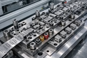
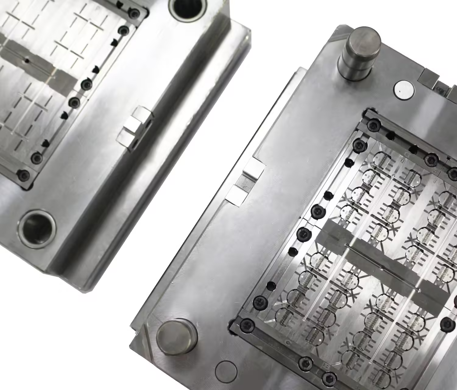
For a tall feature, ask the toolmaker to show the core, its support and the release direction. In injection molding boss design, identify which surfaces need draft and where the final hole dimensions will be checked. Use the relevant injection mold configuration to discuss the physical tooling.
Additionally, record the root section in the injection molding boss design review where the feature joins the floor. If the proposed rib introduces a new thick intersection, compare another support arrangement rather than treating the added volume as an automatic improvement. Coordinate that review with the part designer and moldmaker.
Specify the core geometry for the chosen fastener
Measure the pilot hole at the defined depth
First, identify where the supplier’s hole diameter applies. A drafted pilot hole changes diameter with depth. State the measurement location and drawing direction so the inspection team can compare the molded feature with the intended engagement region.
For a worked dimensional reference, TR’s published table gives the following starting geometry for a 3.0 mm Plas-Tech 30-20 screw. These figures are supplier-specific guidance and require application review. The supplier notes that dimensions may change with material properties and design constraints.
| Feature | Supplier relationship | Listed value | Drawing review |
|---|---|---|---|
| Boss inner diameter | 0.8 × screw diameter | 2.4 mm | Confirm resin and the measurement depth. |
| Boss outer diameter | 2 × screw diameter | 6.0 mm | Review the root and adjacent wall geometry. |
| Thread engagement | 2 × screw diameter | 6.0 mm | Check usable engagement in the tolerance stack. |
| Counterbore diameter | Screw diameter + 0.2 mm | 3.2 mm | Separate the entry region from useful thread length. |
Next, compare the supplier recommendation with molded samples. In injection molding boss design, retain the actual hole profile and material condition alongside the nominal drawing. If the pilot hole differs at the entry and the bottom, report both locations.
For the listed reference, the nominal radial wall between a 6.0 mm outer diameter and 2.4 mm inner diameter is (6.0 − 2.4)/2 = 1.8 mm. This arithmetic describes that section only. It does not establish an allowable joint load or an approved wall at a drafted root.
Then check the screw tip and lead-thread envelope at the shallowest available depth in injection molding boss design. If the fastener contacts the bottom while turning, it can confuse the seating decision. Use the specified head-bearing condition and assembly trace to determine whether the actual joint has seated.
Verify the assembly window before release
For plastic screw installation torque, agree on the definitions used in the test report. Record the running or thread-forming portion of the trace, the event where the head seats and the subsequent tightening response. State what failed when the joint was driven to its test endpoint.
As a separate fastener constraint, EJOT’s direct-fastening FAQ discusses the screw’s breaking torque and the distinction between installation and failure observations. Obtain the applicable values and evaluation method for the selected screw. The actual joint also needs to meet its retained assembly function.
For a hypothetical injection molding boss design trial, assume the highest observed torque needed to complete the defined seating event is 0.45 N·m. Assume the lowest observed stripping torque in separate destructive trials is 1.20 N·m. The provisional driver setting to investigate is 0.70 N·m.
| Comparison | Calculation | Result | Interpretation |
|---|---|---|---|
| Setting above observed seating requirement | 0.70 − 0.45 | 0.25 N·m | Nominal separation from the observed seating endpoint. |
| Observed strip threshold above setting | 1.20 − 0.70 | 0.50 N·m | Nominal separation from observed destructive failure. |
| Observed strip-to-seating ratio | 1.20 / 0.45 | 2.67 | Describes these hypothetical observations only. |
Consequently, the proposed setting lies between the two observed endpoints. Before approving injection molding boss design, include driver variation, measurement uncertainty, material variation and the required clamp function in the decision. A nominal separation alone does not qualify the production setting.
If the test endpoint is a cracked boss, stripped plastic thread or fractured screw, identify that mechanism in the result. Retain the assembly speed, screw condition, resin lot and molded dimensions with the trace. For injection molding boss design, keep repeated-use results separately identified if the joint must be serviced.
When deciding how to design a plastic screw boss for production, make a release worksheet with the selected screw, resin, core profile, root geometry, engagement stack and required assembly cycles. Attach the validated setting and its evidence. Define which material, tool or fastener change triggers a review.
Finally, submit the geometry and acceptance record for molded-part production review. For an enquiry to SSP Precision, include the screw drawing, exact resin and mating assembly so the project discussion starts from the actual joint requirements.
Key takeaways
- Link injection molding boss design to the actual screw, resin, assembly stack and service requirement.
- Use supplier-specific dimensions as a documented starting point, then verify the molded geometry and assembly behavior.
- Retain seating, destructive failure and functional acceptance evidence before releasing a setting.
Frequently asked questions
Can one plastic screw installation torque serve all resin grades?
Validate the setting for the selected screw, resin and geometry. Record the material and conditioning used in the evidence, and review changes through the agreed control process.
Does a larger boss always make the joint better?
Review the load path and local molding sections together. In injection molding boss design, a geometry change needs both an assembly assessment and a molded-part inspection before approval.
Can the torque comparison predict retained clamp load?
The comparison describes the observed torque endpoints. Demonstrate the required retention or clamp function with an agreed measurement or assembly test under the intended service conditions.