






Accept ejector pin marks against the named surface, its function and an agreed inspection method. A visible witness on a hidden wall and damage on a locating face require different decisions. Define the appearance zones, document the pin-contact proposal and keep cosmetic approval separate from dimensional and functional acceptance.
Illustrative application study: the housing, zones, dimensions and inspection decisions below are hypothetical engineering examples. They are not SSP project records or measured production results. The proposed worksheets help an OEM and its moldmaker agree what evidence will close an approval.
This guide explains how to inspect ejector pin marks on a molded housing without treating every circular impression as the same defect. Start with the product drawing and the customer’s acceptance requirements, then assess the observations on representative parts.
Ejector pin marks need a surface-specific acceptance map
First, identify which surfaces the user sees in the installed product. Add surfaces exposed during servicing and assembly. Then map the locating, sealing and bearing interfaces. In this review, a hidden surface does not automatically become an unrestricted place for tool contact.
For technical context, Protolabs describes how ejection contact can leave marks and how pin position, material and local geometry influence the proposal. Its process-specific pin configurations are manufacturer guidance, not a statement about an SSP tool.
Next, give each proposed contact site a stable identifier on the part model. Record the cavity and the inspection orientation with that identifier. This lets an engineer connect ejector pin marks on a sample with the corresponding tooling location without relying on an unannotated photograph.
For the illustrative housing, define zone A as the visible outer face, zone B as the internal review area and zone C as a functional rim. These are project labels. They do not adopt a standardized cosmetic class or establish an allowable mark depth.
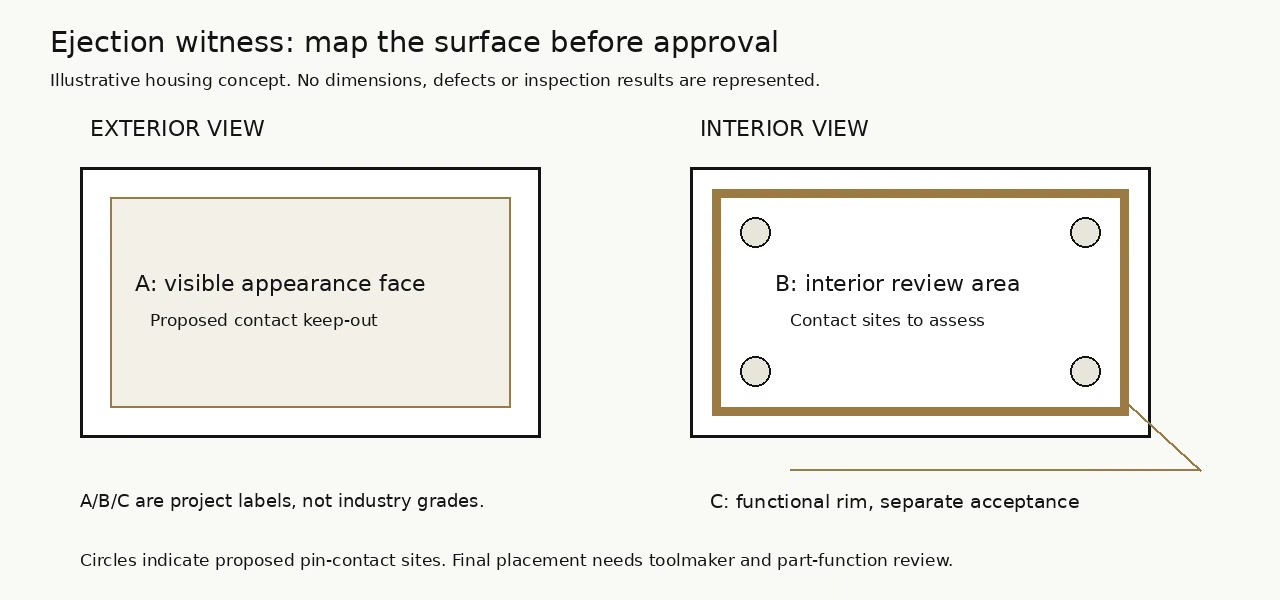
Before approving ejector pin marks, ask the product owner to decide whether each zone permits a visible witness, requires a separate dimensional check or excludes contact entirely. Keep the answer on the same drawing revision as the proposed ejection layout.
| Zone | Surface role | Decision to document | Evidence before release |
|---|---|---|---|
| A | Visible outer face | Whether any contact witness is permitted | Agreed viewing method and approved reference sample |
| B | Internal wall | Allowed appearance and local geometry | Site-specific image, dimensional result where required, damage review |
| C | Functional rim | Keep-out boundary and interface requirement | Drawing check and application-specific functional evidence |
| Transition | Boundary between zones | Which requirement governs a mark crossing the boundary | Annotated layout and written disposition |
Separate a witness from discoloration and deformation
First, describe what is actually observed: a ring, raised area, depression, gloss difference, color change or altered shape. Avoid writing only ‘bad pin mark’ in the report. A useful record gives location, appearance, extent and the condition in which the observation was made.
BASF’s demolding-problems reference distinguishes impressions, gloss changes, whitish discoloration and material damage. It associates unfavorable release with several possible tooling and process conditions. Therefore a photograph alone should not be treated as proof of one root cause.
Investigate stress whitening separately
If stress whitening appears near a contact site, open a damage investigation rather than approving it as an ordinary tooling witness. Record whether cracking, permanent deformation or a functional discrepancy is also present. Use the resin, geometry and release evidence to select the next investigation.
Then compare the appearance observation with the local section and the ejection record. BASF identifies inadequate contact area, unfavorable positioning and release difficulties among relevant causes. That supports checking the system; it does not prescribe one pin diameter or cooling time for every resin.
For ejector pin marks that are purely a repeatable geometric witness, compare the feature with the intended drawing and approved sample. For ejector pin marks accompanied by stress whitening, keep the cosmetic disposition open until the responsible engineer has evaluated the damage concern.
Additionally, record the opposite face of the wall when assessing ejector pin marks. Recommend checking whether a proposed correction changes its shape or appearance. Keep the original and revised sample identities so that removing a visible witness on one side does not silently close a different requirement on the other.
Review ejector pads against the actual load path
First, ask the toolmaker to show the contact face, release direction and nearby wall section. Protolabs explains that flat pin ends acting on angled surfaces can require raised or recessed contact regions. Its examples illustrate why contact geometry and visible surface geometry need to be reviewed together.
Next, compare the proposed ejector pads with the actual available area. Mark nearby ribs, openings, thin walls and assembly keep-outs. Request a section through a contoured site rather than assuming that a circle drawn on the model represents a flat bearing region.
For ejector pin marks on a cosmetic face, review whether an alternative contact location is feasible. Do not instruct the toolmaker simply to move a pin into a hidden corner. Require the revised proposal to show how the part is supported during release and how the new site is inspected.
Then review ejector pads beside the wall-thickness and release requirements. A local geometry change should be evaluated against both the molded part and the physical injection mold design. Keep the tooling decision separate from approval of the finished housing.
For example, propose comparing the existing contact concept with another support arrangement at the same drawing review. Record what changes in contact position, local section and access. This is a recommended design-review method, not evidence that either arrangement has passed a molding trial.
Before changing the finish to conceal ejector pin marks, retain the original appearance requirement and its purpose. The separate mold-finish selection guide covers finish references. Here, the question is whether the resulting contact witness is accepted on the named surface.
Build a controlled inspection and measurement record
First, agree the cosmetic inspection conditions with the customer: part condition, viewing orientation, lighting, distance, observation time and reference sample. State which inspection is visual and which uses measurement. Keep those conditions unchanged when comparing samples offered for the same approval.
As an example of customer-specific practice, GE Grid Automation’s cosmetic inspection document defines viewing procedures and appearance zones for its own supply chain. Its limits do not become general SSP requirements. Obtain the procedure that actually governs the purchased component.
Next, identify the measurement reference when ejector pin marks have a height or depth requirement. State whether the value is relative to a local fitted surface, a specified datum or another agreed reference. Record the sign convention so a protrusion is not confused with a depression.
For a hypothetical numerical review, assume the customer proposes a maximum positive witness height of 0.10 mm on one internal site. Assume a reported height of 0.08 mm and an uncertainty allowance of 0.03 mm. These are invented example inputs for decision planning, not recommended tolerances or laboratory results.
If the parties agree a conservative rule requiring reported height plus the stated allowance to stay within the limit, the comparison is 0.08 + 0.03 = 0.11 mm. It exceeds the assumed limit by 0.01 mm. Under that particular rule, the evidence would not establish acceptance.
By comparison, an assumed result of 0.05 mm with the same allowance gives 0.05 + 0.03 = 0.08 mm, leaving 0.02 mm to the assumed limit. This closes only that hypothetical dimensional comparison. It does not demonstrate acceptable appearance, release behavior or assembly function.
| Record | Reported height | Allowance | Upper comparison | Limit | Disposition under this rule |
|---|---|---|---|---|---|
| Example X | 0.08 | 0.03 | 0.11 | 0.10 | Acceptance not established |
| Example Y | 0.05 | 0.03 | 0.08 | 0.10 | Dimensional comparison satisfied only |
Consequently, do not approve ejector pin marks merely because the displayed instrument value is below a limit. Agree how measurement uncertainty is handled before testing. The arithmetic above is a deliberately stated example decision rule, not a reproduction of a standard or a universal conformity procedure.
When recording how to inspect ejector pin marks, retain the instrument method, local reference, specimen support and reported allowance beside the result. Also identify the cavity, contact site, resin grade, color and sample condition. These fields make later comparisons traceable.
Close the release decision with matched evidence
First, assemble a release sheet containing the drawing revision, zone map, contact proposal, sample identities and unresolved observations. Assign separate decisions for appearance, geometry and function. For ejector pin marks, a single ‘approved’ photograph should not replace those distinct acceptance records.
Then define a sampling plan for ejector pin marks with the responsible quality engineer. Include the cavities and production conditions relevant to the approval question. State how many samples will be examined and why. This guide does not supply a universal sample count or claim that one accepted part demonstrates process capability.
If a tool or process change is proposed to address ejector pin marks, identify the change and the evidence it requires. Compare samples under the same agreed method, then repeat the affected functional and dimensional checks. Retain the rejected or superseded sample reference for traceability.
Next, define the triggers for review: a resin or color substitution, tooling repair, contact-location change or revised appearance requirement. Record who can approve a deviation and whether it is temporary. Keep the disposition tied to its stated scope instead of converting it into a permanent undocumented concession.
Finally, take the annotated acceptance package into the injection molding production discussion. For a review with SSP Precision, provide the part model, material specification, critical surfaces and required evidence. This starts the enquiry from a reviewable engineering question.
Key takeaways
- Evaluate ejector pin marks by named surface, function and agreed viewing method.
- Separate geometric witness, discoloration and deformation before choosing a correction.
- Keep hypothetical height calculations distinct from actual inspection results.
- Release the drawing, appearance reference and evidence together, with change-control responsibilities.
Frequently asked questions
Can hidden ejector pin marks be accepted automatically?
No automatic acceptance is proposed. Check the hidden surface’s assembly role, local dimensions and damage criteria. A hidden site may still be functionally important, so its release needs the evidence specified for that surface.
Which cosmetic inspection conditions should the drawing identify?
Identify the agreed part condition, appearance zone, viewing orientation, lighting, distance, observation time and reference sample. Keep the customer-approved procedure with the drawing, and state which observations require separate dimensional or functional checks.
Does a satisfactory height result prove that ejector pin marks are harmless?
It establishes only the stated dimensional comparison under its agreed method and decision rule. Review appearance, damage and the required assembly function separately before releasing the component.