





Place the injection molding parting line where the tool can release the part and the resulting seam will clear critical surfaces. Review the actual route against sealing lands, mating faces and visible walls. On the drawing, specify where a witness is allowed and check mismatch and flash separately.
When deciding how to specify a mold parting line, begin with the tool opening direction and the assembled part. Mark the surfaces that must stay clear. Then compare each proposed route on the full model before selecting one for the drawing.
Identify the injection molding parting line on the part
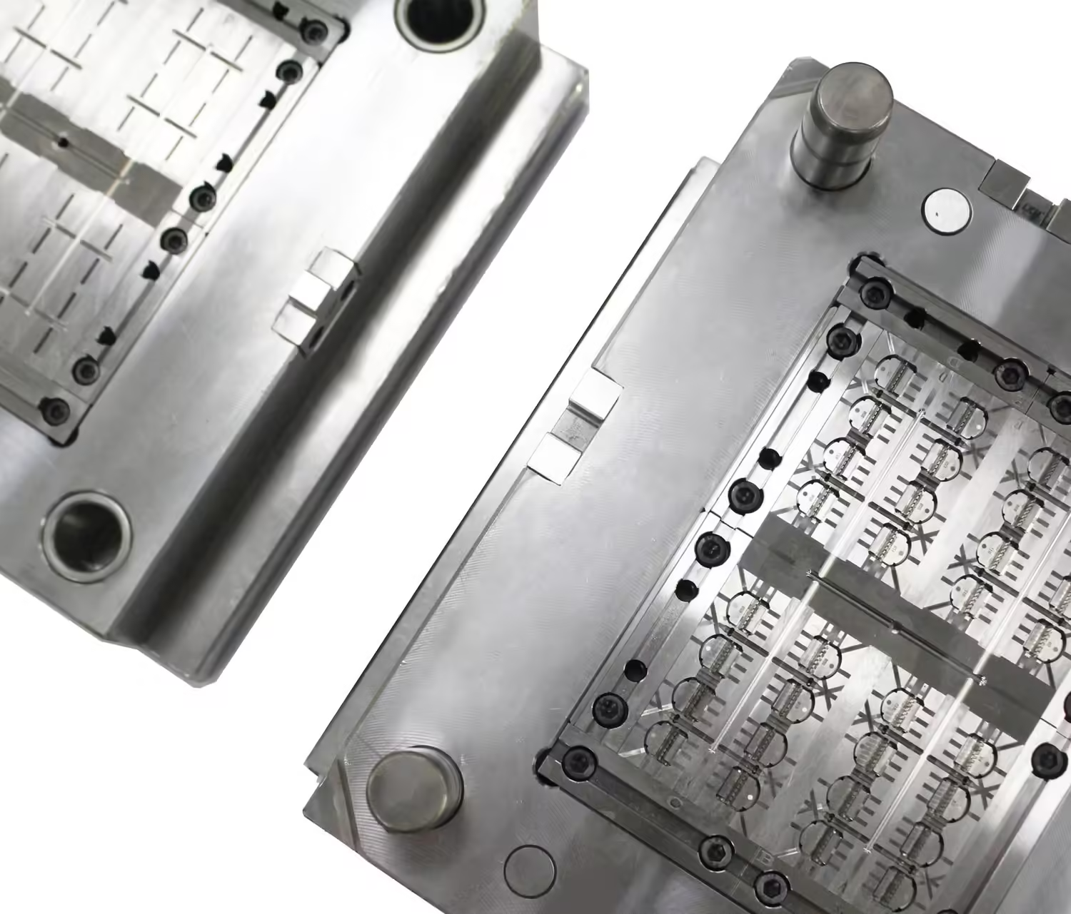
The injection molding parting line is the trace of a mold separation interface on the molded part. Protolabs’ parting-line guide illustrates how the opening direction and part geometry shape that trace. Its examples show how a seam can be conspicuous across a smooth radius and less noticeable at an exterior edge.
First, distinguish the interface in the tool from what you see or measure on the part. A parting line witness mark can be visible even when the surrounding surfaces meet the dimensional requirement. Parting line mismatch is an offset between surfaces formed on opposite sides of the seam.
By comparison, flash is excess resin that projects from an edge or seam. A weld line comes from flow fronts rejoining. The ProMold Plastics glossary distinguishes these features. At an injection molding parting line, log the step, excess resin and appearance as separate observations if they occur at the same location.
For example, a fine seam may be acceptable on a hidden face but still need reviewing if it crosses into a sliding fit. Identify how the assembly moves past the injection molding parting line. Mark where an outward step could contact the other part, even when the seam is hard to see.
Compare mold split routes against the mating surfaces
Next, label the surfaces by function on the CAD model. Mark the visible wall, sealing land, locator faces and insertion envelope. If a surface must remain uninterrupted by the injection molding parting line, define the protected area with dimensions or a clearly identified feature boundary.
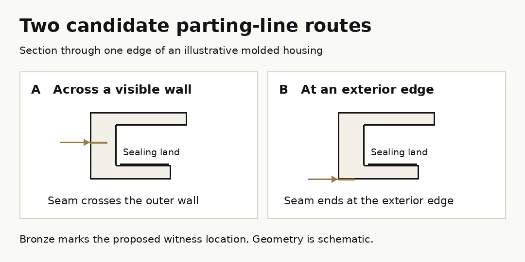
For the first mold split candidate, follow the exterior wall in the illustrative housing below. The seam crosses an exposed surface. For the alternative, bring it to the outside edge and review where the tool must separate around the rest of the housing.
Then check the tool opening direction, draft on both sides and any geometry that would catch during release. The Xometry injection molding design guide discusses keeping the line simple and away from critical functional areas. When changing the injection molding parting line, ask the moldmaker to show the interface and opening motion in section.
| Candidate | Surface consequence | Tooling question | Evidence needed |
|---|---|---|---|
| A, visible wall | Seam crosses the finished exterior. | Can both sides release along the proposed opening axis with the intended wall geometry? | CAD cross-section and approved appearance reference at the wall. |
| B, exterior edge | Seam can be less conspicuous. Check clearance to the mating shell at the edge. | Can the full route stay off the sealing land and clear any lock or return without an unacceptable tooling change? | Section with the mating part, tool interface and assembly clearance. |
In this example, prioritize the edge route for review because it keeps the visible wall clear. Before approving the injection molding parting line, trace the candidate all the way around the housing. At a return or opening, ask the supplier to identify where the tool surfaces touch and what features each side forms.
If both routes interfere with a critical face or require a difficult release, compare a product geometry change with a tooling change. Ask for an annotated mold split proposal and check its fit with the actual injection mold configuration. Use the draft-angle guide to review the affected walls.
Document the permitted route and inspection limits
When showing how to specify a mold parting line on a production drawing, use a named view or section with a model revision. Mark the allowed route and the areas the seam must avoid. Then assign inspection stations at features that matter, such as an assembly lead-in or a change in surface direction.
Measure parting line mismatch at the specified section
First, agree which cross-section and direction will be used to measure parting line mismatch. For a planar wall, the inspection plan can compare the two adjoining surfaces along the approved measurement axis, omitting any flash fin. For a curved surface, use an agreed nominal surface and evaluation method rather than comparing arbitrary points on the radius.
For example, consider a locally planar zone on the housing at station S1. The drawing permits a step of 0.10 mm at this station. The two reference levels are +0.03 mm and −0.05 mm from the same local reference, evaluated along the defined axis.
Then take the absolute difference: |+0.03 − (−0.05)| = 0.08 mm. The part is 0.02 mm below the example step limit. These values are hypothetical drawing inputs and readings. They illustrate the calculation and do not establish a standard limit for an injection molding parting line.
Separately, agree on how to measure unwanted resin. For example, a thin fin may project sideways at an edge. Specify the direction of projection relevant to contact in the assembly, along with the region and inspection stage. Record the fin separately even if the underlying step falls within its limit.
| Item | Define on the drawing or inspection plan | Evidence at first article |
|---|---|---|
| Permitted path | Marked drawing view, protected boundaries and model revision. | Trace the witness on the part and mark any departure from the route. |
| Surface offset | Station, measuring axis, evaluation region and allowable step. | Report both reference levels, absolute difference and decision. |
| Flash | Projection direction, allowable extent and whether to inspect before or after finishing. | Report the largest observed projection in the named area, including the measurement location. |
| Appearance and fit | Viewing conditions, approved boundary sample if applicable, and mating check. | Record visual assessment and fit separately from step and flash. |
Review molded parts before tool acceptance
During the first trial, compare the actual injection molding parting line with the approved views. Confirm its route through corners and transitions. If the proposed witness has moved, ask whether the current samples still establish fit and appearance at the intended release condition.
Next, record the cavity, resin, finish condition, part revision and inspection setup with each measurement. For an injection molding parting line on a visible face, agree whether the appearance check uses a reference sample or defined viewing conditions. A measured step and an appearance approval answer different questions.
If an injection molding parting line meets the step limit but shows a fin in a protected zone, document both findings. Check whether that fin enters the mating envelope before deciding whether deburring, a tool review or a change to the approved route is appropriate. If post-processing is allowed, specify which acceptance checks are repeated afterward.
Before releasing the injection molding parting line, log fit evidence at the actual mating surface. A part that slides into a fixture may still have a seam crossing a protected area. Use the drawing’s requirements to decide which observations need approval and which need further work.
Finally, use the matched drawing, sample and inspection record when requesting production molding support. For a tooling discussion with SSP Precision, include the mating model and permitted witness zones so the proposed route can be reviewed against assembly needs.
Key takeaways
- Approve the injection molding parting line on the full model with its opening direction and protected surfaces visible.
- Give the seam route, surface step and excess resin separate criteria.
- Use the metrology, cosmetic and mating evidence together when releasing the tool.
Frequently asked questions
Can a parting line witness mark be acceptable?
Yes. Compare its position and appearance to the approved criteria. Check any dimensional requirement or excess resin separately at the specified location.
Is placing the seam at an edge always the best choice?
Evaluate the injection molding parting line at the proposed edge in section and on the full tool model. The edge can help hide a witness, while the tooling review still needs to establish release and confirm clearance to the mating part.
Can I use the example step limit on a different housing?
Set the limit for the actual surface, mating geometry and inspection method. The example gives one way to compare readings taken along a specified axis against a hypothetical drawing requirement.