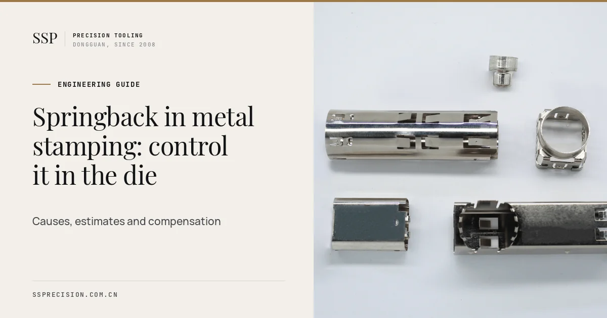
Springback is the reason a bracket drawn at 90 degrees comes out of the die at 93, and the reason a flange that looked perfect in the CAD model twists on the checking fixture. Every bent metal part springs back a little when the punch lifts. The job of the die designer is to know how much, and to build that knowledge into the steel.
This guide explains the physics of springback in plain terms, shows how it changes with material and geometry, gives a method to estimate it before tooling, and sets out the seven methods our die designers use to control it, from simple overbending to simulation-based compensation of the die faces. It ends with a checklist for part designers, because the cheapest correction is the one made on the drawing.
- Springback grows with yield strength and with the ratio of bend radius to thickness, and falls with elastic modulus.
- Aluminum and advanced high strength steels spring back several times more than mild steel.
- Tight radii, bottoming or coining, and stretching the wall all reduce springback at its source.
- Overbending and restriking correct the remaining angle error in the die.
- For complex AHSS parts, forming simulation and die face compensation before cutting steel save weeks of tryout.
What springback is and why it happens
When sheet metal bends, the outer fibres stretch and the inner fibres compress. Near the neutral axis in the middle of the thickness, the strain is small enough to stay elastic. Further out, it passes the yield point and becomes plastic. When the punch retracts, the plastic strain stays, but the elastic strain recovers, like a spring releasing. That recovery opens the bend angle and increases the radius. This is springback.
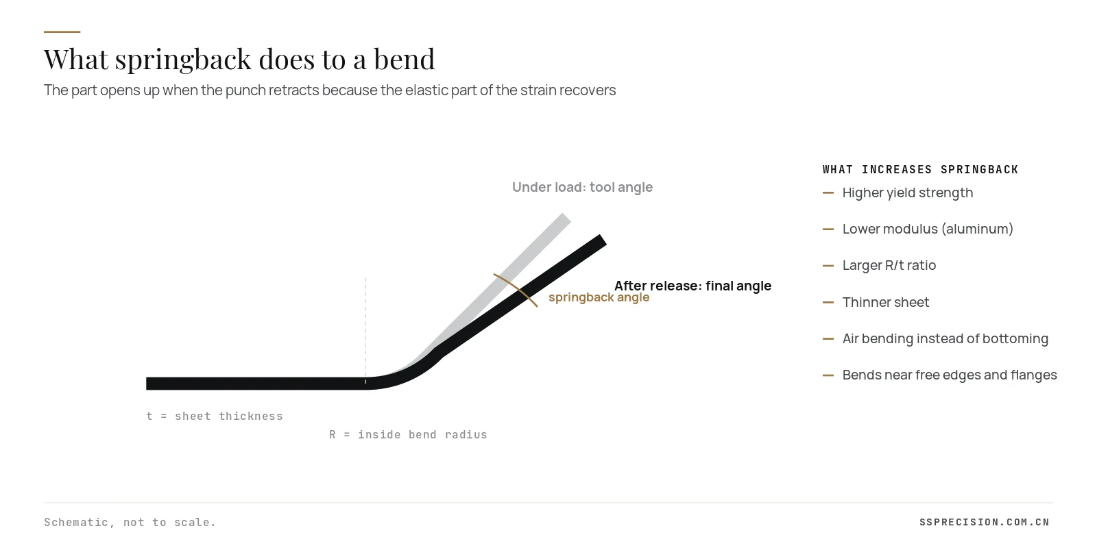
Two consequences follow directly. First, anything that increases the elastic share of the bend, such as a large radius relative to thickness or a strong material, increases springback. Second, anything that pushes more of the section into plastic deformation, such as a tight radius, coining pressure or tension along the wall, reduces it.
The variables that drive springback
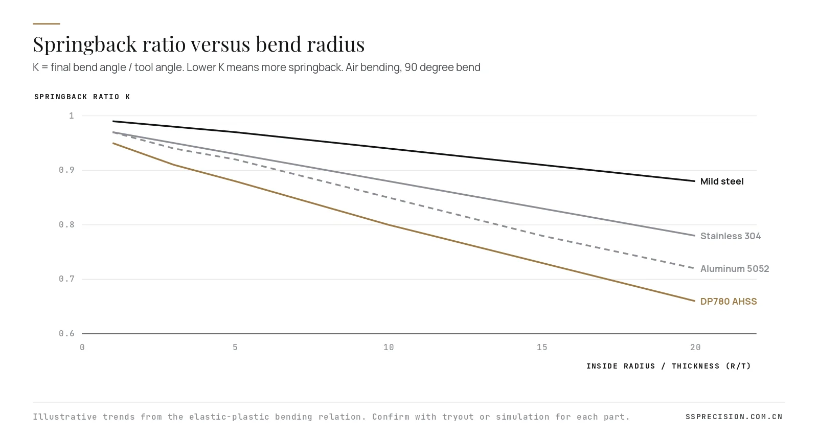
Engineers usually summarize springback with the ratio K, the final bend angle divided by the tool angle. K equal to 1 means no springback; lower values mean more. Several variables move it:
- Yield strength: the higher the yield, the larger the elastic strain at the moment of unloading. Moving from a 200 MPa mild steel to a 780 MPa dual phase steel can triple the springback angle.
- Elastic modulus: aluminum’s modulus is about a third of steel’s, so for the same yield strength it springs back about three times as much. Titanium behaves similarly.
- Radius to thickness ratio: a bend with R/t of 1 is mostly plastic; at R/t of 10 or 20, far more of the section is elastic, and the recovery climbs steeply.
- Thickness: for a fixed radius, thinner sheet has a higher R/t and springs back more.
- Work hardening: materials that harden strongly, such as austenitic stainless, carry higher stresses at the end of the bend and recover more.
- Process: air bending leaves the most springback, bottoming less, and coining the least.
Estimating springback before building the die
For simple V and L bends, a classic relation from elastic-plastic bending theory gives a useful first estimate of how the radius opens up:
A worked example: 1.5 mm mild steel, yield 220 MPa, E 210 GPa, bent over a 3 mm radius to 90 degrees. The term Ri·Y/(E·t) is 3 × 220 / (210,000 × 1.5), or about 0.0021. The cubic term is negligible, so Ri/Rf is about 0.994 and the part springs back by well under a degree. Repeat the calculation for 1.5 mm DP780 with a yield of 500 MPa over a 6 mm radius and the term rises to about 0.0095; springback is then around 3 degrees. For 5052 aluminum with a 6 mm radius the lower modulus gives a similar result.
The formula ignores work hardening, anisotropy, friction and the way the part is supported, so it is only a starting point. For simple brackets it is usually within a degree. For flanges on curved parts, sidewalls of drawn channels and anything in AHSS, forming simulation is the reliable tool, and even then first tryout parts are measured before the die is finished.
| Material | Typical yield | Elastic modulus | Relative springback |
|---|---|---|---|
| Low carbon steel (DC01, SPCC) | 140 to 280 MPa | 210 GPa | Low, baseline |
| HSLA steel (S355MC type) | 355 to 420 MPa | 210 GPa | About 1.5 to 2 times mild steel |
| Stainless 304 | 215 to 300 MPa, hardens fast | 193 GPa | About 2 times mild steel |
| DP780 / DP980 AHSS | 450 to 700 MPa | 210 GPa | About 3 to 4 times, plus sidewall curl |
| Aluminum 5052-H32 | 160 to 190 MPa | 70 GPa | About 2.5 to 3 times mild steel |
| Copper alloys (C5191, C7025) | 400 to 700 MPa | 110 to 130 GPa | High in thin spring tempers |
Relative values for comparable bend geometry. Always use the certificate values of the actual coil.
Angular springback, sidewall curl and twist
Elastic recovery is not one problem but several:
- Angular change: the flange angle opens after a bend. This is the simplest form and the easiest to correct.
- Sidewall curl: in U channels and hat sections, the wall bends as it is drawn over the die radius and straightened again, leaving a curve. It is common in AHSS and hard to fix by overbending alone.
- Twist: asymmetric parts rotate about their long axis as residual stresses rebalance.
- Flange and edge wave: stretched or shrunk flanges on curved edges buckle or open.
Each has a different cure, which is why the first step in any such problem is always to measure the part on a fixture or scanner and compare it to the nominal, rather than to adjust the die by eye.
Seven ways to control springback in the die
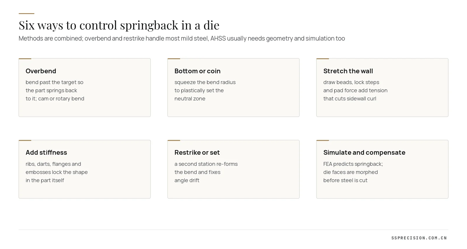
1. Overbend
The most common correction: bend past the target so the part springs back to it. For a 90 degree flange that springs back 3 degrees, the die forms 87. In a progressive die this is done with a wiping station followed by an overbend station, or with a cam or rotary bender that swings past vertical. Overbending is cheap and adjustable, but it only corrects angle, not curl.
2. Bottom or coin the bend
Squeezing the bend radius between punch and die at the bottom of the stroke drives the whole section into plastic deformation and sets the angle. Coining with a small bead or a reduced clearance at the radius is very effective in thin material, but it needs press tonnage and it thins the bend slightly, so it must be allowed for in the part design.
3. Stretch the wall
Adding tension along the wall while it is formed, using draw beads, lock steps or higher binder and pad force, moves the whole section past yield and greatly reduces sidewall curl. A post-stretch of just 2% is often enough. This is the standard cure for channels and hat sections in high strength steel.
4. Add stiffness to the part
Ribs across a bend, darts in the corner, embossed beads along a flange and a return flange on a free edge all lock the shape into the part. They cost nothing in the die once designed and they keep working when the coil properties change. We suggest them at design review whenever the part function allows.
5. Restrike or set station
A second forming station that re-forms the bend at a slightly different angle, or sets the radius with a pad, trims out residual error. In progressive dies a set station with an adjustable insert lets the toolroom tune the angle during production without rebuilding the die.
6. Simulate and compensate the die faces
For complex parts, sheet metal forming simulation predicts springback from material data. The die faces are then morphed in the opposite direction, so that the part springs back to nominal. Two or three simulation loops before steel is cut typically remove most of the tryout iterations on AHSS parts.
7. Control the process and the material
Recovery varies with the coil. A yield strength spread of 50 MPa within a specification can move a flange by a degree or more. Tight material specifications, coil certificates checked against the die tryout material, and servo press motion with a short dwell at the bottom of the stroke all narrow the spread.
Why advanced high strength steels are different
Dual phase, complex phase and martensitic steels have changed automotive stamping. Their yield strengths of 450 to over 1,000 MPa let designers cut weight, but they bring three forming effects that mild steel rules do not predict. The elastic modulus of these steels drops slightly as they are plastically strained, by as much as 10 to 20% after forming, which increases elastic recovery beyond what the handbook modulus suggests. They harden differently when the strain direction reverses, as it does when a wall is bent over a die radius and then straightened, which is the root of sidewall curl. And their strength varies more from coil to coil, so a die that is perfect on one coil may be off on the next.
The practical response is to use material models calibrated for these effects in simulation, to rely on geometry and wall tension rather than overbend alone, and to keep the set stations adjustable. Tooling steel and coatings must also rise to the forming loads, which are two to three times those of mild steel.
Progressive and transfer dies handle it differently
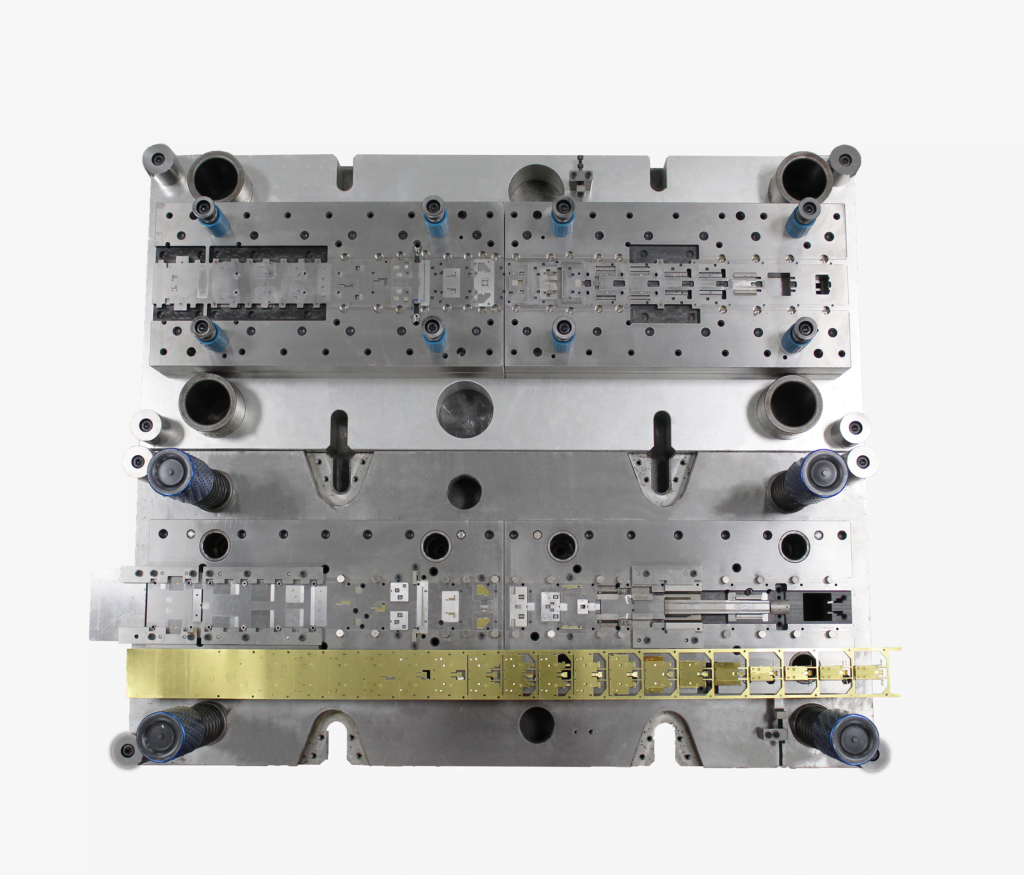
In a progressive die the part stays attached to the carrier strip, which restrains it during forming and gives a stable reference for measurement. Bends can be split across several stations, each doing part of the angle, which spreads the work and makes correction easier. The limitation is space: there is only so much room in the strip for extra restrike stations.
In a transfer die the part is free between stations. That allows deep draws and forming from several directions, but the part can move as it is transferred and its residual stresses release as soon as it is cut from the blank. Transfer dies therefore often carry a dedicated restrike or calibration station at the end, and the fingers and nests must hold the part accurately so that correction is repeatable.
Material data you need for an accurate prediction
Estimates and simulations are only as good as their inputs. For each part we ask for, or test, the yield and tensile strength, uniform and total elongation, the hardening curve, the anisotropy values in three directions, and the thickness tolerance. For high strength grades, cyclic hardening data and the variation of modulus with strain make a measurable difference. When the customer’s coil certificate differs from the data used in the die design, we re-check the forming stations before production rather than after the first rejected lot.
An example from production
A mounting bracket in 2.0 mm S420MC high strength steel had two 90 degree flanges with a tolerance of ±0.5 degrees. The first design used air bending with a 4 mm radius and produced flanges at 92.5 to 93.5 degrees, drifting with each new coil. We reduced the radius to 3 mm, added a coining bead at the bend in the final forming station, introduced two small stiffening darts agreed with the customer, and made the set insert adjustable in 0.1 mm steps. Production parts now run at 90 ±0.3 degrees across coils, and the toolroom has a documented setting for each coil strength band.
Measuring and correcting springback at tryout
Tryout is where estimates meet reality. Our routine is to form first parts, scan or measure them on a checking fixture, compare with the CAD nominal, and correct the die in a planned sequence: angle first, then curl, then twist. Each correction is recorded so the die can be re-tuned the same way after maintenance.
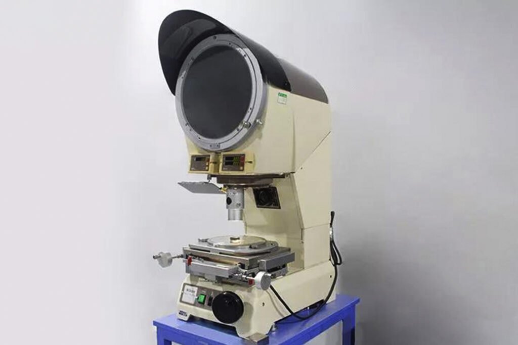
Measuring is easy to get wrong. Parts measured free-state behave differently from parts clamped on a fixture, and customer fixtures sometimes clamp springback away. Agree the measuring condition with the customer at the start of the project. On our optical profile projector and CMM, we report bend angles free-state and clamped where that difference matters.
Designing parts that spring back less
Many springback problems are cheaper to solve on the drawing than in the die. Before a part is released for tooling, check these points:
- Use the smallest bend radius the material allows; one to two times thickness for mild steel is usually fine.
- Specify angle tolerances only as tight as the assembly needs; ±0.5 to 1 degree is achievable in production, tighter costs more.
- Add stiffening ribs or darts on bends in high strength or aluminum parts.
- Avoid long unsupported flanges and bends close to free edges.
- Choose the lowest strength grade that meets the function; strength costs springback.
- Dimension from datums that the forming die locates, not from features formed later.
Fighting springback on a current part?Send the drawing, material certificate and measurement report. Our die designers will review the forming sequence and propose corrections.
Request a quoteHow SSP designs dies for springback
Every forming station we design carries an allowance from our material database and the relation above, refined by simulation for high strength and aluminum parts. We build adjustability into the stations most likely to need tuning, such as set inserts and cam angles, and we keep the tryout record with the die. That approach applies across our progressive dies, transfer dies and the full stamping die manufacturing program, and our design and manufacturing team reviews part designs for springback before tooling starts.
For related topics, read our stamping die design guide and our comparison of progressive and transfer dies. The theory behind elastic recovery is summarized in this reference on springback.
Springback FAQ
What causes springback in sheet metal bending?
During bending part of the material thickness stays elastic. When the punch retracts, that elastic strain recovers and opens the bend angle and radius. Higher yield strength, lower elastic modulus and larger radius to thickness ratios increase it.
How much springback should I expect?
Mild steel bent to a tight radius typically springs back less than 1 to 2 degrees on a 90 degree bend. Stainless, aluminum and advanced high strength steels can spring back 3 to 8 degrees or more, especially at larger radii.
How do you compensate for springback in a stamping die?
By overbending, bottoming or coining the bend, stretching the wall with beads or pad force, adding stiffening features to the part, restriking, and for complex parts by simulating springback and compensating the die faces before cutting steel.
Does coining eliminate springback?
Coining the bend radius drives the section fully plastic and reduces springback to a very small value, but it needs high tonnage and thins the bend slightly. It works best on thin material and small bends.
Why is springback worse in aluminum?
Aluminum’s elastic modulus is about one third of steel’s. For the same yield strength, the elastic strain at unloading is about three times larger, so the part recovers more.