

Micro gear injection molding design should begin with a measurable tooth-accuracy requirement and the assembled gear pair, not an outside-diameter tolerance alone. Define the gear geometry, locating datums, inspection conditions and functional acceptance together. Celanese distinguishes spacing, profile and runout errors in plastic gearing; each answers a different question. [1] Celanese.
The study considers a small external spur-gear pair for a compact mechanism. Its purpose is to show how a drawing becomes an evidence plan: what must be specified, what a trial must distinguish, and what remains unresolved after a promising dimensional report. The same reasoning can guide supplier discussions without implying that one generic tolerance will qualify every small molded gear.
Tooth-accuracy review in brief
- Specify the mating pair and its installation, not only the loose gear.
- Separate nominal geometry, measured deviation and operating acceptance.
- Agree a datum and measurement method before committing to final tooling.
- Keep cavity, shot and material identity attached to trial samples.
- Use dimensional and functional evidence as separate release gates.
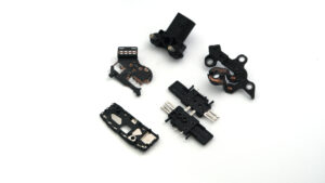
The featured photograph shows an existing mold insert from SSP’s media collection as tooling context. It is not a gear cavity or evidence of this hypothetical study.
Set the micro gear injection molding design inputs
Start with the mechanism’s task. Record what moves, how it is supported and when the direction reverses. Describe the expected duty rather than writing “precision transmission” on an otherwise incomplete drawing. Ask the product owner to identify the important outcomes: delivered motion, permissible lost movement, assembly effort, noise, wear or another explicitly defined function.
Keep these requirements separate from supplier preferences. A proposed inspection technology is not itself a product requirement. Conversely, a requirement that cannot be evaluated needs a method discussion before it becomes a release criterion. Identify who approves each item and which drawing or test document controls it.
| Input group | Proposed record | Question left open if omitted |
|---|---|---|
| Gear pair | Both drawings, tooth counts, module, pressure angle and intended modifications | What geometry is supposed to mesh? |
| Installation | Shaft arrangement, locating features, support and housing interfaces | How will the inspected gear be located in use? |
| Duty | Torque history, speed, reversals and duration | What functional evaluation represents the mechanism? |
| Environment | Temperature, exposure and material condition | Which conditions belong on the approval record? |
| Acceptance | Named characteristics, limits, methods and decision owner | Who can distinguish pass, fail and evidence required? |
For plastic micro gear tooth accuracy, resist the temptation to copy a general molded-part tolerance table into every drawing field. This study recommends a characteristic-by-characteristic agreement. AGMA’s public scope for 905-A17 explicitly states that the inspection document does not establish geometry tolerances or a quality classification. [2] AGMA. Naming that document therefore cannot supply missing acceptance limits.
Check a nominal spur-gear example before discussing capability
Use a simple, explicitly bounded model. Assume two external, unmodified standard spur gears with the same module and compatible pressure angle. Select a hypothetical module of 0.20 mm, 20 pinion teeth and 40 gear teeth. These numbers demonstrate arithmetic; they are not an SSP manufacturing specification or a recommendation for the reader’s mechanism.
For this nominal model, reference diameter equals module multiplied by tooth count. Circular pitch equals π multiplied by module, and the nominal center distance is half the sum of the reference diameters. These relationships are given in Celanese’s spur-gear tables. [1] Celanese. Reference diameter is not the directly measured tooth-tip diameter.
| Quantity | Input or calculation | Result |
|---|---|---|
| Module | Assumed for both gears | 0.20 mm |
| Pinion reference diameter | 0.20 mm × 20 teeth | 4.00 mm |
| Gear reference diameter | 0.20 mm × 40 teeth | 8.00 mm |
| Nominal center distance | (4.00 mm + 8.00 mm) / 2 | 6.00 mm |
| Tooth-count ratio | 40 / 20 | 2:1 |
| Circular pitch | π × 0.20 mm | Approximately 0.6283 mm |
| Ideal tangential force | 2 × 0.002 N·m / 0.004 m | 1 N |
All numerical inputs are hypothetical. Nominal relationships: Celanese, Tables 8.4, 8.6 and 8.7. These calculations do not establish a workable tooth form, operating center distance, strength or life.
The ratio is a nominal kinematic relationship, not a prediction of efficiency, accuracy or life. The example does not include profile shift, intentional clearance, housing deviation, shaft movement or environmental dimensional change. If those inputs differ, the design owner must review the working geometry rather than treating 6.00 mm as an automatically approved assembly setting.
A torque calculation is not a tooth-strength approval
Suppose the pinion transmits a hypothetical 0.002 N·m at its 0.004 m reference diameter. Using tangential force = 2 × torque / diameter gives 1 N. Celanese provides this torque-force relationship. [1] Celanese. The units must be consistent: substituting 4 as though millimeters were meters would change the result incorrectly.
That 1 N is only an idealized tangential-force input. No tooth-root stress, deflection, fatigue life, contact temperature or transient overload has been evaluated. A responsible release record would identify the additional analysis and component trials needed; it would not turn this arithmetic into a claimed allowable gear load.
Translate tooth accuracy into distinct evidence questions
A drawing should distinguish the tooth system from the surfaces that locate it. Celanese discusses pitch error, profile error and runout, and explains that a composite mesh check can reveal overall variation without identifying every source. [1] Celanese. This is why one successful check should not silently stand in for the whole approval plan.
For the illustrative mechanism, propose separate records for tooth spacing, flank form, the gear’s relationship to its locating bore and the axial seating arrangement. The designer must choose the controlled characteristics and terminology appropriate to the geometry. The table below is a discussion worksheet, not a substitute for a purchased standard or a universal list of required measurements.
| Evidence question | Proposed inspection discussion | What it must not be assumed to prove |
|---|---|---|
| Are tooth positions acceptable? | Agree the pitch-related characteristic and evaluation convention | Complete flank form or operating life |
| Is the flank shape acceptable? | Compare specified regions with the agreed nominal geometry | Correct installation or material strength |
| Is the tooth system located correctly? | Evaluate its relationship to the agreed functional datum | Every individual tooth characteristic |
| Does a controlled mesh check pass? | Record the master, setup and composite criterion | The unique cause of an unfavorable trace |
| Does the installed mechanism function? | Use the agreed assembly and operating test | Unmeasured geometry or long-term durability |
Plastic micro gear tooth accuracy should remain tied to the chosen evaluation conditions. Specify the drawing revision and the condition in which samples are accepted. KHK cautions that temperature and humidity can alter dimensions and backlash in plastic gears. [4] KHK. That is a reason to define conditions, not permission to borrow a catalog’s tolerance as a guarantee for a different molded part.
Turn the drawing into a controlled tooling and molding review
Bring the geometry, material proposal and inspection worksheet into the same discussion. Ask the moldmaker to explain where the split, gate, ejection contacts and cavity identifiers would sit relative to functional features. Review these as proposals requiring approval. Do not assume that a generic gear illustration reveals a workable gate, release direction or cavity design.
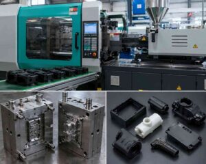
For the physical tool, use SSP’s injection mold tooling range as a starting point for a project-specific discussion. Confirm the proposed configuration against the actual drawings. This article does not claim that SSP has built the hypothetical gear pair or owns a particular gear-inspection system.
The molding trial should answer defined questions, not merely produce a tray of visually complete parts. Record the material identity, preparation instructions, tool revision and proposed process conditions. Keep the selected resin supplier’s current instructions with the trial plan. Avoid applying one generic material shrinkage percentage to all tooth, hub and bore requirements without component evidence.
| Review item | Proposed evidence request | Decision before irreversible tool work |
|---|---|---|
| Split and release | Marked concept showing functional faces and release direction | Accept the proposed witness and release arrangement |
| Gate and vestige | Location, removal proposal and inspection access | Agree the allowable affected region |
| Geometry adjustment | Trial-to-drawing comparison with cavity identity | Separate demonstrated deviation from a guessed correction |
| Sampling | Shot sequence, cavity map and retained samples | Agree which evidence can be compared |
| Change control | Documented tool and process revision | Define the retest triggered by each change |
As an organizational example, suppose three cavities supply five consecutive shots in each of two agreed trial conditions. That is 3 × 5 × 2 = 30 gears for one part design. This is an illustrative allocation, not a statistically justified sample size. Retain the identity of every piece; thirty mixed samples would not preserve the proposed cavity-by-condition comparison.
State the study question before selecting those two conditions. They might distinguish a candidate process change, but this article does not specify machine settings or claim that two trials establish a validated process window. When the question is gate selection rather than gear acceptance, use the separate gate-location design guide instead of repeating its entire scope here.
Build a micro gear metrology plan that can be repeated
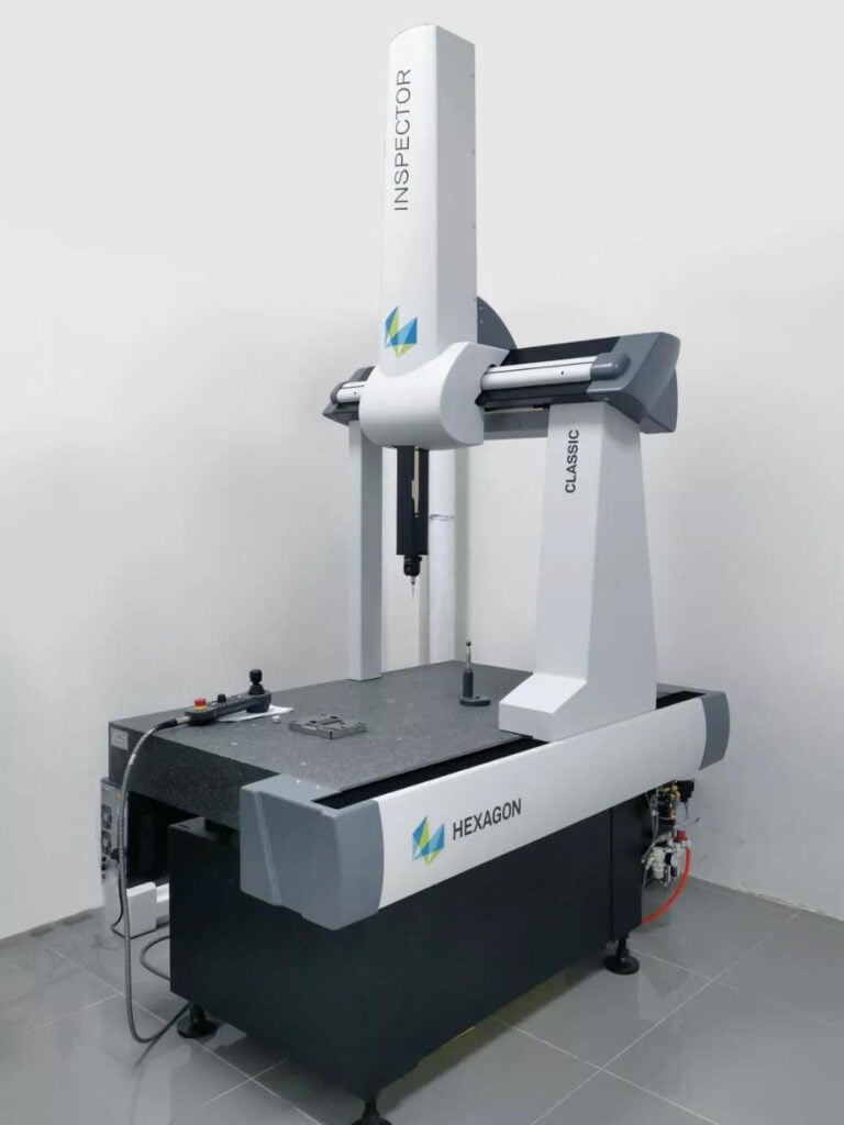
Micro gear metrology starts with the characteristic and datum, followed by a justified instrument and setup. Ask the inspection provider to demonstrate that the proposed approach can evaluate the actual tooth size, surface and required region. Keep any unresolved access or evaluation limitation on the approval record rather than hiding it behind an instrument brand.
ZEISS describes application-specific gear measurement and CAD-to-actual comparisons of plastic gears using computed tomography. [3] ZEISS. This establishes available measurement approaches in the market, not that every CT or coordinate system can meet this hypothetical task. It also does not establish SSP equipment ownership or measurement uncertainty.
Write the setup into the record
For micro gear metrology, propose recording the locating arrangement, orientation, inspection program revision, nominal model and evaluation settings. Ask the provider to explain which regions are included and excluded. If a report changes after remounting, investigate the setup and evaluation before deciding that the cavity requires modification.
A useful comparison exercise would retain the same identified samples while the team checks a repeat measurement and a remounting sequence. The inspection specialist should define repetitions, analysis and suitability criteria. This article deliberately provides no universal repeatability percentage, uncertainty ratio or pass threshold.
Keep the original report together with the decision. Where a result is close to a specified limit, request the agreed decision rule and the relevant measurement evidence. Do not round an unfavorable value into acceptance or replace a missing characteristic with a screenshot that looks convincing. Escalate unresolved measurement questions to the responsible specialist.
Interpret the evidence before releasing the gear pair
Compare like with like: same drawing, sample condition, datum convention and evaluation method. Separate cavity-related patterns from changes that appeared after a documented process or tool revision. A proposed explanation is not a demonstrated cause; record the follow-up trial that could confirm or challenge it.
The recommended release has separate dimensional, assembly and operating gates. AGMA’s public scope excludes material strength, strength-related processing effects and flash from the inspection document’s coverage. [2] AGMA. Therefore a gear-measurement report alone should not be described as complete product validation.
| Release gate | Evidence proposed for review | Disposition if incomplete |
|---|---|---|
| Definition | Approved pair drawings, material and acceptance methods | Hold the missing definition |
| Geometry | Traceable characteristic reports and identified samples | Resolve deviation or measurement uncertainty |
| Assembly | Agreed locating arrangement and installation checks | Review the full interface |
| Operation | Defined duty and environment with recorded observations | Run the missing evaluation |
| Change control | Approved revisions and retest triggers | Do not treat an unapproved change as covered |
The practical next step for micro gear injection molding design is a review package containing both gear drawings, the mechanism requirements and the unresolved evidence questions. Discuss production planning through SSP’s plastic-part molding services; use SSP Precision’s tooling and manufacturing overview for broader company orientation. Ask for project-specific confirmation before agreeing any capability or acceptance commitment.
Frequently asked questions
Does an outside-diameter result establish tooth accuracy?
No. The proposed approval separates the gear’s geometry questions. Celanese distinguishes pitch, profile and runout behavior, so a tooth-tip diameter alone cannot replace that evidence. [1] Celanese.
Does AGMA 905-A17 supply a universal micro-gear tolerance?
Its public scope explicitly says it does not establish geometry tolerances or a quality classification. Specify the appropriate characteristics and acceptance with the design and inspection owners. [2] AGMA.
Can a composite mesh check diagnose every error?
Celanese describes composite checking as useful for overall evaluation but limited in isolating the source. Use the agreed complementary checks when diagnosing a tooling or part issue. [1] Celanese.
Which micro gear metrology system should be selected?
Select it against the actual characteristic, geometry and evidence requirements. ZEISS describes several application-specific approaches; this study does not endorse one instrument as universally suitable. [3] ZEISS.
Were the example gears manufactured or tested by SSP?
No. This is an illustrative engineering study. Its arithmetic and worksheets are teaching examples, not a customer case, dimensional report or verified production result.
References and study limits
Primary sources support the attributed observations and nominal relationships. The workflow, matrices, sample allocation and release gates are original proposed engineering practices, not reproduced standard procedures. Obtain current supplier guidance and the applicable licensed standards for a real project.
- Celanese Celcon Acetal Copolymer Design Guide, particularly Tables 8.4–8.6 and Sections 8.2–8.6.
- AGMA905-A17 Inspection of Molded Plastic Gears: public scope, public abstract and scope only.
- ZEISS Gear Measurement Services.
- KHK Spur Gears Technical Information.