

O-ring groove design in molded plastic should be checked at the assembled gland, including the seal tolerance and any local opening between the mating faces. Groove depth alone does not define the space available to the seal. Minnesota Rubber & Plastics distinguishes the machined groove depth from the total axial gland depth in a face seal. [2] Minnesota Rubber & Plastics.
This application study follows a hypothetical thermoplastic cover with a static face seal. Its purpose is to turn a proposed groove into a reviewable tolerance calculation, inspection plan and validation record. It does not provide a standard groove size or an approved sealing design for a particular pressure, fluid or service life.
Groove review in brief
- Define the pressure direction, seal compound and assembly before selecting the groove.
- Separate groove depth from assembled gland height.
- Check squeeze and gland fill at the stated tolerance extremes.
- Inspect the locating surfaces and local opening as well as the groove.
- Keep dimensional approval separate from functional sealing validation.
Define the scope of O-ring groove design in molded plastic
Begin with an assembly section and a written operating question. Identify the pressure side, mating components, seal location, closure method, intended medium and exposure conditions. Recommend assigning an owner to each requirement rather than beginning with a groove copied from a different housing. Preserve the selected seal supplier and compound identity alongside the part drawing.
A static face seal is the selected teaching case, not a universal model for every O-ring. Minnesota Rubber & Plastics describes an axial seal as a face seal and distinguishes static applications from moving applications. [3] Minnesota Rubber & Plastics. Do not transfer the example to a reciprocating rod, rotating shaft or other seal configuration without a new application review.
Pressure direction belongs on the section. The manufacturer’s face-seal guidance explains how positioning the ring against the groove wall opposite the applied pressure influences the selected seal and groove diameters. [2] Minnesota Rubber & Plastics. This study therefore leaves those diameters for supplier review; a cross-section calculation alone does not select the correct ring diameter or pressure-side restraint.
For the plastic cover, recommend documenting how the closing faces locate and which features establish the inspection datum. Ask the designer to identify the permissible local face opening in the assembled condition. Keep that allowance distinct from a free-state flatness result, a screw-torque instruction and a prediction of cover deflection. State how the assembly owner will justify the connection between those records.
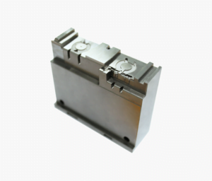
The featured photograph contains existing molded component examples from SSP’s collection. It provides general component context; none is presented as the hypothetical cover, an O-ring gland or evidence of a sealing test.
Calculate squeeze from the assembled gland height
For this original teaching model, let d be the free O-ring cross-section, g the groove depth below the closing land and e a local opening above that land. The available axial gland height is h = g + e. When the faces contact in the defined section, e = 0. Minnesota Rubber & Plastics likewise separates application clearance from the groove-depth calculation for a face seal. [4] Minnesota Rubber & Plastics.
Plastic sealing groove dimensions: a hypothetical tolerance stack
Assume d = 2.00 ± 0.08 mm and g = 1.50 ± 0.05 mm, with e allowed to vary from 0 to 0.05 mm. The nominal calculation uses a closed local face, e = 0. These are invented inputs, not dimensions taken from a seal standard, supplier chart or SSP capability statement. All values refer to the same assumed reference condition.
The geometric compression fraction is S = (d − h) / d. Multiply by 100 to express squeeze as a percentage. Minnesota Rubber & Plastics gives the equivalent compression relationship and its minimum/maximum tolerance combinations. [3] Minnesota Rubber & Plastics. Applying it axially here follows the face-seal orientation already defined; it is not a prediction of contact stress or leakage.
| Quantity | Nominal closed face | Minimum-squeeze combination | Maximum-squeeze combination |
|---|---|---|---|
| Free cross-section d | 2.00 | 1.92 | 2.08 |
| Groove depth g | 1.50 | 1.55 | 1.45 |
| Local opening e | 0.00 | 0.05 | 0.00 |
| Gland height h = g + e | 1.50 | 1.60 | 1.45 |
| Geometric squeeze S | 25.00% | 16.67% | 30.29% |
For example, minimum squeeze is (1.92 − 1.60) / 1.92 × 100 = 16.67%, rounded. Maximum squeeze is (2.08 − 1.45) / 2.08 × 100 = 30.29%. The nominal 25% result therefore does not keep the entire assumed stack at 25%. These endpoints bound the stated combinations; they do not describe their probability in production.
Parker’s Section 3.6 gives 30% as the maximum recommended static squeeze for most elastomers, with application qualifications. [1] Parker. If the real application adopted that recommendation, the example’s maximum would require review rather than being rounded into acceptance. Do not assume the recommendation qualifies an unspecified compound, plastic cover or closure load.
Recommend returning to the drawing owner with alternatives to evaluate: different tolerances, revised gland geometry, a different seal selection or a better-supported closing arrangement. Recalculate the complete stack after each proposed change. Selecting one favorable nominal dimension while retaining the unfavorable tolerance combination would not resolve the question demonstrated here.
Evaluate gland fill independently of squeeze
Gland fill compares seal volume with the available gland volume. Parker’s Section 3.7 explains why space must remain for effects including seal swelling, thermal expansion and tolerance accumulation. [1] Parker. A satisfactory squeeze calculation does not, by itself, establish adequate remaining volume.
Use a deliberately simplified model to expose that second question. Assume a straight rectangular gland with width b = 2.60 ± 0.05 mm, the same effective mean circumference for seal and gland, zero installed stretch and no swelling. Ignore wall draft and corner radii only for this arithmetic example. The real design must account for its actual geometry and material condition.
Under these assumptions, the common circumference cancels from the volume ratio. The free seal area is A = πd² / 4, the available rectangular section is b × h, and the fill estimate is F = πd² / (4bh) × 100%. The manufacturer’s area-based gland-fill equations support this simplified comparison. [3] Minnesota Rubber & Plastics. It must not be applied unchanged where the stated assumptions do not hold.
| Quantity | Nominal | Lower-fill combination | Higher-fill combination |
|---|---|---|---|
| d, mm | 2.00 | 1.92 | 2.08 |
| b, mm | 2.60 | 2.65 | 2.55 |
| h, mm | 1.50 | 1.60 | 1.45 |
| Seal area A, mm² | 3.1416 | 2.8953 | 3.3979 |
| Available section b × h, mm² | 3.9000 | 4.2400 | 3.6975 |
| Calculated fill F | 80.55% | 68.29% | 91.90% |
The maximum uses the largest assumed seal section and the smallest assumed gland section. Its remaining space is 100 − 91.90 = 8.10%, rounded. Parker calls for at least 10% void in an elastomer gland in Section 3.7. [1] Parker. The example therefore fails that particular screening check even before omitted effects are evaluated; it is not a release-ready design.
Do not solve this arithmetic problem by assuming the rubber can occupy any missing volume. Recommend asking the seal specialist to review the actual installed geometry, dimensional limits, compound behavior and exposure. A revised width can change fill without resolving a squeeze, restraint or support issue. Keep each acceptance question separate in the design record.
Translate the sealing section into mold and drawing requirements
Mark the groove bottom, sidewalls, closing lands and mating face on the drawing. Recommend identifying the controlled characteristics and allowable affected regions before approving the mold concept. Ask how the split, gate, release direction and ejection contacts relate to those regions. Treat each proposed arrangement as a review item rather than assuming a generic tooling photograph proves suitability.
Minnesota Rubber & Plastics notes that molded-part warpage varies with the thermoplastic material. [5] Minnesota Rubber & Plastics. For this proposed cover, request evidence about the actual geometry and condition rather than adopting a broad warpage allowance as the local opening e. Keep the material proposal, molding condition and assembled support arrangement attached to that review.
Specify a functional surface requirement separately from a cosmetic appearance label. The supplier’s plastic-finish guidance describes glossy and textured choices and their relationship to appearance and ejection. [6] Minnesota Rubber & Plastics. This study recommends a separate seal-interface review: identify which surface is evaluated, the required method, any directional features and the approval owner. It provides no universal roughness value.
For the physical tool, discuss the marked section with SSP’s injection mold tooling team. Request project-specific confirmation of the proposed cavity features and inspection access. This link identifies the tooling discussion; it does not assert that SSP has produced or validated the example gland.
Where the wider molding process needs a defined operating region, use the separate scientific molding process-window guide. Keep this study focused on gland geometry and assembly acceptance rather than recreating general molding-process or defect-troubleshooting content.
Build a molded gland inspection record
Inspect the assembly-related definition, not only a groove-depth number
Recommend an inspection worksheet that names the drawing revision, material condition, datum, locating method and each reported characteristic. Include the groove depth and width as defined, relevant land geometry and the evidence used to justify local opening. Ask whether the selected setup can reach and evaluate the actual surfaces without substituting a different feature.
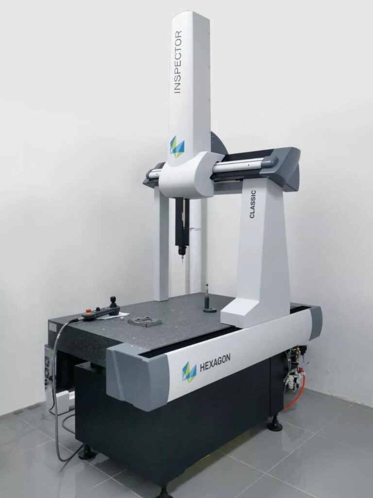
Do not claim a particular measuring machine is automatically suitable. Ask the inspection provider to explain access, probe or optical configuration, evaluation method and uncertainty for the required characteristics. Retain the original reports and the agreed disposition rule, especially where results approach an acceptance limit. This is a proposed review practice, not an asserted measurement capability.
Keep cavity and sample identities through inspection and assembly. If a part is measured free and then clamped, label the records accordingly rather than mixing their results. Recommend retaining the seal lot and mating-part identity with each assembly result so that a later investigation can reconstruct what was evaluated.
Use a repeatable review checklist:
- Confirm the part, seal and mating-component revisions.
- Record the dimensional and conditioning assumptions.
- Verify how each dimension enters the squeeze and fill models.
- Identify incomplete measurements or unapproved deviations.
- Retain the original evidence with the engineering decision.
The goal is a traceable decision, not a larger pile of readings. If a report lacks a datum or the assembly state needed by the model, resolve that omission before using its value in the stack. Likewise, do not replace an unfavorable local result with an average from unrelated positions.
Validate the seal and release the assembly
Dimensional inspection answers the drawing questions it actually evaluated. For this application, recommend a separate functional plan approved by the product and seal owners. Define the medium, pressure direction, exposure, duration, loading sequence, assembly condition and acceptance method required by the real product. This article deliberately supplies no universal leak-test pressure, duration or allowable leakage.
Minnesota Rubber & Plastics recommends application-specific verification where conditions such as high pressure, large tolerances or different fluids require it. [4] Minnesota Rubber & Plastics. Use that guidance to define the necessary evidence with the responsible specialists. A calculated squeeze percentage is not a test result, and a passing initial assembly is not automatically a service-life approval.
Before release, review three distinct outcomes: the design is adequately defined, the manufactured components meet that definition, and the assembled system meets its functional requirements. Recommend documenting any restrictions and the evidence still required. Do not mark an untested exposure as passed because another check was satisfactory.
Agree what changes trigger a new review: seal compound or source, resin grade, tool geometry, molding setup, mating component, assembly procedure or required service condition. Assign an owner to decide the retest scope. Preserve the basis for that decision rather than extending approval to every future version by default.
For a project discussion, send the marked assembly section, seal specification and acceptance questions to SSP’s plastic-part molding service. Refer to SSP’s tooling and manufacturing capabilities for broader project orientation. Ask for confirmation of the actual proposed resources and deliverables before agreeing a manufacturing or validation commitment.
Frequently asked questions
Is groove depth the same as assembled gland height?
Only in the defined contacting-face condition of this example. With a local opening, h = g + e. The supplier’s face-seal guide distinguishes groove depth from the total available axial gland space. [2] Minnesota Rubber & Plastics.
Does a nominal 25% squeeze approve the proposed groove?
No. The hypothetical tolerances here produce 16.67% to 30.29% geometric squeeze. The actual compound, assembly and acceptance requirements remain to be evaluated.
Why calculate gland fill separately?
It addresses available volume rather than compression alone. In this simplified example, the higher-fill combination reaches 91.90%; that result needs review and is not evidence of an acceptable gland.
Can a cosmetic finish label qualify the seal interface?
This study recommends a separate functional surface definition and inspection agreement. An appearance label does not document which sealing characteristic or acceptance method was evaluated.
Was the cover manufactured or leak-tested by SSP?
No. This is an illustrative engineering study with hypothetical inputs and original calculations. Photographs provide general context, not project or test evidence.
References and study limits
Sources support the attributed definitions, equations and manufacturer guidance. The example dimensions, definition sketch, calculations, inspection worksheet and release workflow are original teaching material. Supplier limits require application-specific interpretation; none is an SSP capability claim.
- Parker O-Ring Handbook, ORD 5700, Sections 3.6 and 3.7, printed page 3-9.
- Minnesota Rubber & Plastics: O-Ring Seals for Face Seal Applications.
- Minnesota Rubber & Plastics: Defining Factors in Sealing Applications, compression and gland-fill equations.
- Minnesota Rubber & Plastics: Groove Design, O-Ring Seals.
- Minnesota Rubber & Plastics: Warpage, qualitative material dependence only; no general dimensional allowance adopted.
- Minnesota Rubber & Plastics: Plastic Surface Finish.