

A scientific injection molding process window is a documented range of processing conditions linked to acceptable parts, with evidence explaining its boundaries. Start by defining the required part responses, separate commanded settings from observed behavior, then challenge the proposed operating region under a controlled trial plan. RJG explains why machine settings alone may not describe conditions inside the cavity. [1] RJG.
This guide develops a practical review workflow for a thermoplastic part. It covers trial preparation, factor selection, evidence collection and release decisions. It does not prescribe a universal molding recipe, reproduce a regulated validation procedure or promise that one small experiment establishes long-term production capability.
Process-window review in brief
- Define quality responses and measurement conditions before choosing factor levels.
- Record actual process behavior alongside the machine recipe.
- Keep cavity, shot, trial and material identities attached to samples.
- Treat a trial matrix as evidence to evaluate, not automatic approval.
- Release the operating region with a recovery and change-control plan.
Define the scientific injection molding process window
Begin with a signed question: which changes may the process tolerate while still delivering the required part? A useful study brief names the drawing revision, exact material, tool revision, intended machine and the quality characteristics being evaluated. Recommend assigning an owner to each acceptance decision so that an attractive sample cannot substitute for an unresolved requirement.
For a housing, the response list might include a locating dimension, cover assembly, visible sink and a defined functional test. Select the list from the real product requirements. Do not assume that part weight represents every one of those outcomes. As a review practice, ask what evidence would reveal a failure for each requirement and what would remain unknown after that evidence passed.
Separate three records: the proposed factor region, the results actually observed and the region authorized for production. Keeping those records distinct prevents an untested supplier recommendation from appearing as a qualified limit. It also makes a later review possible without reconstructing the meaning of a colored chart.
AMB describes process-window development using melt temperature and packing pressure, followed by holding-time and cooling studies. [3] AMB. Those are useful examples of study subjects, not instructions to vary the same factors on every part. Choose the study around the failure question and the permitted operating envelope for the actual resin, mold and machine.
Recommend writing the exclusions beside the objectives. For example, a dimensional process-window exercise might not address chemical resistance, lifetime fatigue or every cosmetic surface. Keep any separately required product validation visible. A reviewer should be able to tell what the study supports and which release decisions still need other evidence.
Establish a baseline that another engineer can reconstruct
Create a setup record before collecting the comparison samples. Include material grade, lot, color and preparation record; tool and insert revisions; cavity map; machine and control configuration; and the relevant auxiliaries. Record which entries are specified, which were checked and which remain assumptions. This is a proposed traceability structure, not a claim that a particular certificate is mandatory for every molding job.
Injection molding process stability: commands and observations
A setpoint is a command; an observation is the value or trace recorded by a stated method. Put them in separate worksheet fields. For a pressure record, name whether the reported value is hydraulic pressure, a machine-reported plastic pressure or an in-cavity sensor result. Define the units and source rather than labeling every column simply “pressure.”
RJG describes cavity-pressure measurement as a way to observe filling, packing and variation inside the mold. [1] RJG. That supports asking what the chosen signals actually reveal. It does not prove that every installation has those sensors, or that a sensor trace alone qualifies the finished product. Request project-specific confirmation of the available instrumentation and its suitability.
AMB’s method separates filling studies from packing and reviews available injection pressure against the pressure needed to maintain the intended fill behavior. [2] AMB. In the proposed baseline review, retain the actual fill-time and pressure records. If a trial does not achieve its intended operating condition, flag that run for review instead of treating its nominal setting as an achieved factor level.
Before sampling, agree a stabilization criterion appropriate to the study. Describe the observations used to decide that a changed condition is ready to evaluate, the handling of intervening shots and the disposition of interrupted runs. Avoid inventing a fixed warm-up shot count that supposedly fits every tool. Preserve the real chronology, including pauses and corrective adjustments.
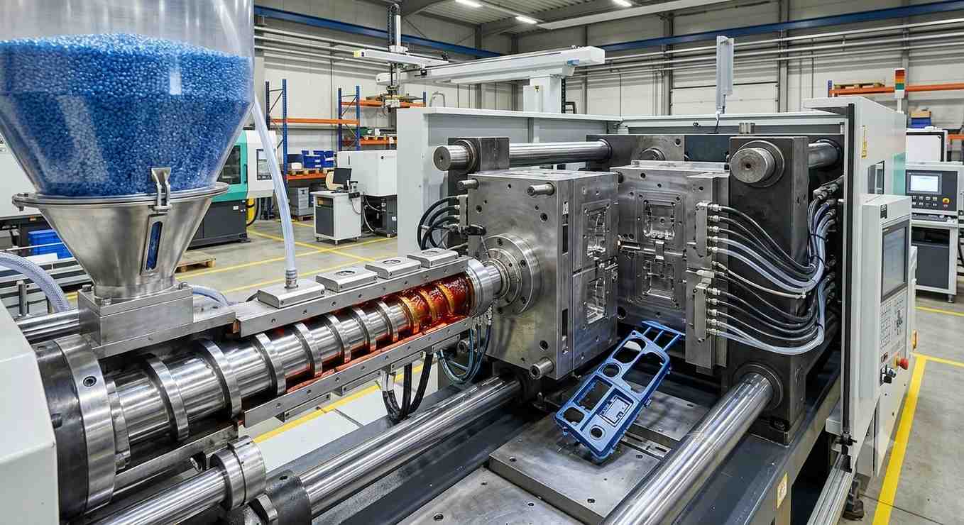
Molding process window validation: factors, responses and limits
For molding process window validation, recommend giving each factor a definition, unit, measurement source and reason for inclusion. Select low and high levels within approved supplier and equipment boundaries. A low level means the lower level selected for this study; it does not mean the lowest setting the machine can display.
Record the remaining conditions as controlled inputs or identified sources of variation. If material, gate geometry and cooling arrangement all change between two trials, the study brief must explain what comparison remains valid. This guide recommends changing the minimum needed to answer the question while documenting unavoidable changes.
Explain what the experiment can distinguish
NIST’s two-level factorial guidance describes testing combinations of factor levels and the associated design matrix. Its centerpoint guidance explains checks for instability and curvature. [4] NIST; [5] NIST. Use those resources with an experimental-design specialist to select a design appropriate to the real question. A convenient worksheet does not establish adequate statistical power.
Consider how hard-to-change temperatures affect the trial sequence. Ask the experiment owner whether blocking, restricted randomization or a different design is appropriate. Document that decision before running the work. Do not rearrange a planned experiment for convenience and later analyze it as though all combinations had been freely randomized.
Keep the response definitions equally precise. For a dimension, name the datum, measuring method, sample condition and reporting precision. For appearance, define the viewing conditions and approval reference. For a functional requirement, identify the assembly, loading sequence and acceptance document. Recommend retaining an explicit “not evaluated” status alongside pass and fail.
Tooling proposals belong in this review too. If the study exposes a question about the physical mold, SSP’s injection mold configurations provide an appropriate starting point for a tooling discussion. Treat any proposed gate, sensor or cooling modification as a documented change requiring its own review. For gate-location selection specifically, use the separate injection molding gate design guide.
Build a numerical matrix without confusing samples and trials
The following original planning example has two continuous factors: A is measured melt temperature, and B is the defined packing-pressure setting. Their actual low, center and high values must be approved for the specific setup; none are supplied here. Codes −1, 0 and +1 represent those agreed levels, not temperatures or pressure units.
Assume a hypothetical two-cavity tool. Propose five consecutive identified shots at each of four factorial combinations and three separately executed center runs. The table lists condition identifiers, not the execution order. It illustrates 2² = 4 corner combinations and a workload calculation using the factorial structure described by NIST. [4] NIST.
| Condition ID | A: coded temperature | B: coded pressure setting | Identified shots | Parts from 2 cavities |
|---|---|---|---|---|
| Corner LL | −1 | −1 | 5 | 10 |
| Corner HL | +1 | −1 | 5 | 10 |
| Corner LH | −1 | +1 | 5 | 10 |
| Corner HH | +1 | +1 | 5 | 10 |
| Center C1 | 0 | 0 | 5 | 10 |
| Center C2 | 0 | 0 | 5 | 10 |
| Center C3 | 0 | 0 | 5 | 10 |
| Total | 7 separately executed conditions | 35 | 70 | |
The arithmetic is 7 × 5 × 2 = 70 parts. This is a resource estimate, not a validated sample-size rule. Do not count seventy pieces as seventy independently established process settings. Record which experimental unit the analysis uses, and ask the experiment owner how shot, cavity and run effects will be treated.
NIST recommends distributing center runs through an experiment to observe stability, rather than randomizing their positions. [5] NIST. For this proposal, plan C1 near the beginning, C2 within the experiment and C3 near the end, with the remaining execution strategy approved by the study owner. Each center run must be executed and documented separately; subdividing one retained bag does not create three repeated trials.
Give every retained part a traceable identifier such as trial, condition, shot and cavity. Reserve separate packaging for samples that experienced an interruption or unapproved change. Recommend checking the labeling system with the inspection team before starting so that dimensional reports can be joined back to the correct process evidence.
Interpret boundary evidence and numerical margins carefully
Review every required response at every executed condition. Recommend a matrix that retains the observations, acceptance decision and unresolved questions for each cavity. A condition with acceptable dimensions but unreviewed function remains incomplete for a release that requires both. Avoid averaging a failed cavity into a passing tool-level result.
A hypothetical dimensional-margin calculation
Assume an example drawing specifies 20.00 ± 0.05 mm. Suppose an entirely synthetic set of observations spans 19.97 to 20.02 mm. These numbers are invented only to demonstrate the calculations below. They are not SSP measurements, a recommended tolerance or evidence that any molding process can hold this dimension.
| Quantity | Calculation or assumed input | Result |
|---|---|---|
| Lower specification limit | 20.00 − 0.05 mm | 19.95 mm |
| Upper specification limit | 20.00 + 0.05 mm | 20.05 mm |
| Specification width | 20.05 − 19.95 mm | 0.10 mm |
| Synthetic observation range | 20.02 − 19.97 mm | 0.05 mm |
| Lower observed margin | 19.97 − 19.95 mm | 0.02 mm |
| Upper observed margin | 20.05 − 20.02 mm | 0.03 mm |
| Range / specification width | 0.05 / 0.10 × 100% | 50% |
The last row is simply a ratio of two widths. It is not Cp, Cpk, a predicted reject rate or a confidence statement. No distribution, stability, uncertainty or representativeness has been established in this arithmetic example. Recommend reporting the raw evidence and its limitations before discussing capability with the responsible quality specialist.
Likewise, acceptable samples at four corners and a center do not logically demonstrate every unsampled point in a continuous region. Ask what model, additional experiments and confirmation work justify the proposed interior. Where responses disagree, use their combined requirements to define the candidate region. Preserve failures rather than drawing a larger rectangle around selected successes.
Keep holding and cooling evidence connected to the selected setup. AMB describes holding-time development through part-weight observations as time increases, then dimensional checks during cooling review. [3] AMB. Bozzelli explicitly notes that not every part should be run with a sealed gate. [6] John Bozzelli. Therefore document the actual gate system and acceptance question rather than making a weight plateau a universal release rule.
Release the operating region with monitoring and change control
For injection molding process stability, recommend approving a package rather than a lone setpoint sheet. Include the setup revision, demonstrated factor levels, selected operating point, supporting samples, inspection records and open restrictions. State who can authorize a deviation and which conditions require a stop, containment or engineering review.
The operating point deserves its own justification. Explain its relationship to the limiting quality responses and the observed variation. Do not assume the arithmetic midpoint of a settings rectangle is automatically the best production choice. Keep the reasoning visible so a future engineer can distinguish an intentional decision from a software default.
Before handover, rehearse the written recovery path with the production team. Ask what record identifies an interrupted run, how suspect parts are separated and what evidence is needed before release resumes. This proposed exercise tests whether the documentation can be used, without claiming that a paper review replaces actual production qualification.
- Confirm the current drawing, resin, tool and machine identities.
- Approve the measured responses and their inspection conditions.
- Retain each executed condition, including deviations and failed samples.
- Explain the authorized region and remaining limitations.
- Define monitoring, reaction and requalification decisions.
Set review triggers for changes to material, equipment, tooling, control logic or acceptance requirements. Determine their impact through the agreed change process rather than declaring every transfer equivalent. A study from one setup is a reference record for the next review, not automatic proof about an untested replacement.
For a supplier discussion, send the study question, part requirements and available trial evidence to SSP’s plastic-part production service. Use SSP’s tooling and manufacturing overview for broader project orientation. Confirm the actual proposed trial resources and deliverables before making any validation commitment.
Frequently asked questions
Is a machine recipe the same as a process window?
This guide distinguishes a commanded setup from an evidence-backed operating region. RJG explains that machine parameters do not always represent cavity behavior. Keep the recipe, observed responses and authorized limits as related but separate records. [1] RJG.
Must every study vary melt temperature and packing pressure?
No universal pair is prescribed here. AMB uses those factors in its process-window example. Select and justify factors for the actual quality question, material and equipment. [3] AMB.
Does the 70-part example establish adequate validation?
No. It is a hypothetical allocation: seven conditions, five shots and two cavities. An appropriate design, repetitions, measurement plan and acceptance evidence must be approved for the real study.
Are center runs interchangeable with corner runs?
They answer different design questions. NIST describes center runs as checks for stability and possible curvature. Preserve their planned placement and separate execution records. [5] NIST.
Does part weight alone qualify an operating region?
The proposed workflow requires the actual product responses, including dimensions or function where specified. AMB discusses weight in holding-time development and dimensions in cooling review; it does not make one weight check a substitute for every product requirement. [3] AMB.
References and limits
Sources support the attributed process and experimental-design concepts. The planning worksheets, numerical inputs, synthetic observations and release recommendations are original teaching material. No source’s machine settings, study outcomes or photographs have been represented as SSP evidence.
- RJG: Injection Molding Process Control and Cavity Pressure Monitoring.
- AMB: Scientific Injection Moulding, Part 1, 3 July 2018.
- AMB: Scientific Injection Moulding, Part 2, 18 July 2018.
- NIST/SEMATECH e-Handbook: Two-level full factorial designs.
- NIST/SEMATECH e-Handbook: Adding centerpoints.
- John Bozzelli, Scientific Molding: Publications, gate-seal experiment note.