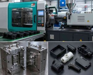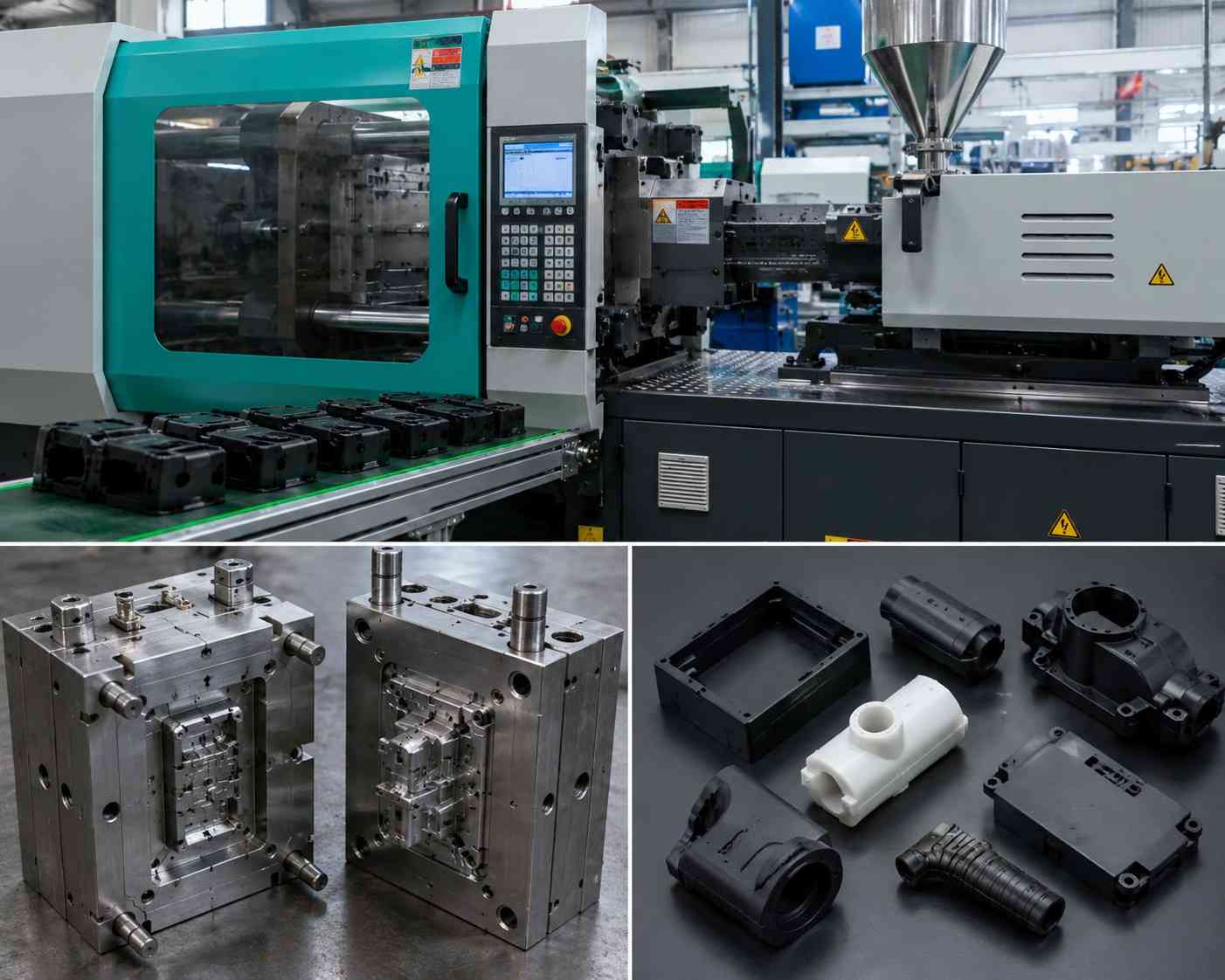
Polypropylene living hinge design succeeds only when material, hinge geometry, flow path, molding conditions, and the durability test are treated as one system. Polypropylene is widely used because thin, oriented PP sections can tolerate repeated flexing, but a material name alone does not establish service life. The selected resin grade, gate location, hinge thickness and radius, molded condition, opening angle, environment, and failure criterion must all be defined and verified on production-representative parts. INEOS, Polypropylene Processing Guide, printed pp. 3-5.
Engineering answer in brief
- Choose an unfilled, hinge-suitable polypropylene grade with the resin supplier, then qualify that exact grade and color package.
- Design the land, radii, recess, and adjoining walls together so the cover reaches its closed position without crushing the hinge into an uncontrolled crease.
- Place and size the gate to create a consistent flow across the hinge web and keep opposing flow fronts from meeting at the hinge.
- Use mold-flow analysis to compare fill patterns, pressure demand, hesitation, and predicted weld-line locations, then confirm the result with short shots and molded parts.
- Define one open-close cycle, angle, rate, environment, inspection interval, and pass/fail rule before testing. A cycle count without those conditions is not a transferable durability claim.
These recommendations apply the hinge geometry and flow principles in INEOS, printed pp. 3-5, Protolabs, and the service-representative testing principle in ASTM D7791-22, section 5.4.
Why polypropylene is used for a living hinge
A living hinge is a thin flexible web molded as part of the two rigid sections it connects. The INEOS processing guide identifies the living hinge as a recognized capability of polypropylene homopolymers and copolymers, and relates PP hinge performance to fatigue resistance, tensile strength, elongation, and orientation in thin molded sections. The same guide states that unfilled materials produce stronger hinges with better appearance than filled grades in its design context. INEOS, Polypropylene Processing Guide, printed pp. 3-5.
That guidance does not mean every PP grade is interchangeable. Homopolymer and copolymer families, additives, color concentrate, recycled content, and processing history can change part behavior. The engineering recommendation is therefore to select a named production grade with the supplier, retain its technical data and lot traceability, and test the molded hinge made with the intended color and approved material recipe. This recommendation follows the broader ASTM principle that fatigue results are suitable for design only when the specimen and test conditions realistically simulate service conditions. ASTM D7791-22, sections 5.1-5.5.
Polycarbonate, ABS, or a soft elastomer should not be substituted merely because a prototype bends once. Protolabs explains that brittle resins may not tolerate hinge flexing, while a very flexible material may lack the stiffness required in the adjoining body. It identifies polypropylene and polyethylene as common choices that balance flexible thin sections with stiffer thick sections. Protolabs, Designing Living Hinges that Fold Flat.
Living hinge thickness, radius, and adjoining geometry
There is no responsible universal living hinge thickness. INEOS publishes starting geometry for its polypropylene context, while also linking hinge dimensions to the desired closing feel and moldability. A designer should use resin-supplier guidance as a starting point, then resolve the exact thickness by filling analysis, tool capability, opening force, and molded-part testing. INEOS, Polypropylene Processing Guide, printed p. 4.
The web cannot be considered in isolation. Protolabs describes hinge thickness and bend radius as interacting variables: a thinner section can flex through a tighter radius, while a poorly recessed hinge can either prevent the adjoining surfaces from closing or be forced into an overstressed crease. Its proposed design logic is to recess the hinge relative to the adjoining surfaces so the closed assembly preserves a controlled bend rather than crushing the web. Protolabs, Factors to Consider and A Paper-Thin Example.
| Decision | What to define | Why it matters | Evidence basis |
|---|---|---|---|
| Resin | Exact PP grade, supplier, color/additive package, permitted regrind or recycled-content rule | Fatigue comparisons are not transferable when the material or specimen preparation differs. | ASTM D7791-22, 5.4-5.5 |
| Hinge web | Nominal thickness, tolerance, width, land length, radii, and recess | Thickness and bend radius jointly control flexibility and whether the assembly closes without an uncontrolled crease. | Protolabs |
| Gate and flow | Gate position, type, dimensions, runner balance, and flow direction across the web | INEOS calls for consistent uninterrupted flow across the hinge web and warns against stressed weld lines. | INEOS, printed p. 5 |
| Use motion | Open and closed angles, dwell, rate, applied hand or actuator load, latch interaction | Fatigue data are useful only when test conditions represent service. | ASTM D7791-22, 5.4 |
| Acceptance | Through-crack rule, functional closure, torque or force drift, appearance limits, cycle target | A count is meaningless unless the failure event and inspections are defined. | Project-specific engineering requirement |
The table separates documented principles from project decisions. It does not prescribe a resin grade, dimension, or life target.
Illustrative application study inputs
Assume a one-piece flip-top enclosure with a molded cover and base. The hypothetical design uses an unfilled, injection-molding-grade polypropylene selected with its supplier. The lid rotates through 110 degrees in service and engages a separate snap latch. The internal engineering target is 20,000 complete open-close cycles at room laboratory conditions, followed by a second test set in the most severe project-defined use environment. None of these inputs is an SSP claim or a general industry requirement.
| Input | Illustrative value | Status | Required confirmation |
|---|---|---|---|
| Part | One-piece flip-top enclosure | Hypothetical | Released CAD and tolerance drawing |
| Material | Unfilled PP, exact grade not yet selected | Hypothetical placeholder | Supplier data, color package, lot and change-control rules |
| Motion | 0 to 110 degrees and back | Hypothetical | Actual use path, dwell, rate, and actuator contact |
| Durability target | 20,000 complete cycles | Hypothetical | Product requirement and risk analysis |
| Specimens | 30 parts per condition | Hypothetical | Statistical rationale and lot coverage |
| Failure | Any through-crack, loss of full closure, or inability to engage the latch | Hypothetical | Approved inspection method and functional limit |
The illustrative workload is simple to audit: 30 specimens multiplied by 20,000 complete cycles equals 600,000 specimen-cycles for one condition. This is a test-execution count only. This study makes no population reliability inference from the hypothetical specimen count.
Mold-flow and gate study before cutting steel
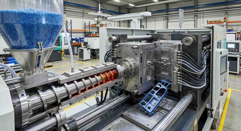
The hinge web is a severe flow restriction. Protolabs explains that pressure can rise upstream of the narrow web, increasing flash risk, while pressure downstream may fall enough to create filling problems. It also warns that placing gates on both sides so opposing fronts meet at the hinge can weaken the hinge region. Protolabs, Potential Problems.
INEOS gives compatible process guidance: hinge gating should produce consistent, uninterrupted flow across the web, and gate location should minimize weld-line formation in stressed regions. The guide also recommends balanced cavity filling and generally moving from thick toward thin sections, while recognizing that integral hinges need specific gate treatment. INEOS, Polypropylene Processing Guide, printed p. 5.
A simulation is useful for comparing alternatives, not for declaring service life. Autodesk states that Gate Location analysis recommends injection locations as preliminary input for a full Fill+Pack analysis. Autodesk also identifies weld-line results as predictions of where flow fronts meet and notes that changing gate positions changes the fill pattern and weld-line position. Autodesk, Gate Location analysis; Autodesk, Troubleshooting weld and meld lines.
Proposed simulation comparison
- Model the released wall, hinge land, radii, gate, runner, and cooling assumptions with the selected material file.
- Compare at least a gate arrangement that drives one continuous front across the hinge with any packaging-constrained alternative.
- Review fill time, pressure demand, hesitation or early freeze risk, temperature through the web, air-trap locations, and predicted weld lines.
- Reject any concept that deliberately places an opposing-flow meeting line on the hinge without a validated reason and test evidence.
- Carry the chosen process window into mold trials, then compare simulation to short shots, fill pattern, flash, hinge thickness, and functional cycling.
Those five steps are an engineering recommendation based on the cited gate and weld-line principles. The actual analysis sequence, mesh, material model, solver settings, and acceptance thresholds must be documented by the responsible simulation engineer.
A reproducible living hinge fatigue test plan
ASTM D7791-22 covers uniaxial fatigue of rigid and semi-rigid plastics and explains that processing, surface condition, stress, specimen depth, frequency, and preparation affect fatigue results. It is not a product-specific living-hinge acceptance standard. Its useful lesson here is methodological: results should be compared only when the preparation and conditions are equivalent, and design use requires realistic service simulation. ASTM D7791-22, scope and sections 5.1-5.5.
For the hypothetical enclosure, the part-level method should define the complete motion rather than borrow a coupon test and call it equivalent. One cycle is defined as moving from fully closed to 110 degrees open, pausing for the specified dwell, and returning to fully closed with the latch either engaged or intentionally bypassed. If the latch is bypassed, the result is hinge-only durability and must not be reported as full closure-system durability.
| Test element | Recorded requirement | Reason |
|---|---|---|
| Specimen identity | Resin grade and lot, color, cavity, molding lot, process revision, date code | Separates material, cavity, and process variation. |
| Conditioning | Time, temperature, humidity, and any chemical or UV exposure | Makes environmental history repeatable. |
| Motion | Angle endpoints, path, rate, dwell, actuator contact, latch state | Defines what one cycle physically means. |
| Inspection | Baseline, scheduled intervals, final check, crack method, closure and latch function | Locates the onset and mode of degradation. |
| Stop rule | Through-crack, incomplete closure, latch failure, unsafe fixture condition, or target reached | Prevents inconsistent operator judgment. |
| Data | Cycles, interruptions, force or torque trend if measured, images, failure location, censoring reason | Supports comparison and root-cause review. |
Suggested sequence for this illustrative study
- Measure hinge thickness at agreed locations and visually inspect every specimen before cycling.
- Record opening and closing force or torque on a defined subset if user feel is a requirement.
- Run a pilot at slow speed to confirm the fixture follows the intended arc without prying or twisting the hinge.
- Cycle the full set under the documented condition, pausing at planned intervals for inspection.
- Photograph the same hinge surfaces and record crack initiation, whitening, permanent set, closure, and latch function using consistent criteria.
- Repeat the test for the second environment only after its temperature, chemicals, dwell, and conditioning history are approved.
The visible whitening or force drift may be useful diagnostic signals, but they are not failures unless the drawing or validation plan defines them as such. Conversely, a part that still opens but has a through-crack fails the hypothetical rule above even if it has not separated completely.
How to interpret mold-flow and fatigue results together
A failure at the same hinge location across several cavities suggests reviewing a common design or flow mechanism. A failure concentrated in one cavity suggests checking cavity-specific thickness, venting, cooling, gate condition, and process balance. These are diagnostic hypotheses, not proof. They must be tested with measured geometry, short-shot or fill-pattern evidence, process records, and fracture location.
| Observed result | First questions | Evidence to collect |
|---|---|---|
| Crack starts at one edge | Is the web thickness or radius asymmetric? Is the actuator twisting the lid? | Section measurements, fixture video, edge-detail images |
| Early failure across all cavities | Is the material recipe correct? Does flow cross the web continuously? Is the bend being crushed? | Material certificate, short shots, gate layout, closed-state section |
| One cavity fails early | Does that cavity differ in fill, cooling, flash, or hinge thickness? | Cavity-marked data, process balance, dimensional map |
| Flash at the hinge | Is local pressure high upstream of the restriction? Is shutoff or clamp behavior adequate? | Fill study, pressure trace, parting-line inspection, tool condition |
| Downstream short shot | Does the thin hinge freeze or hesitate before the far section fills? | Short-shot sequence, fill time and temperature plots, actual process settings |
| Passes lab cycling but fails in use | Did the lab omit temperature, chemicals, dwell, misuse, latch loads, or actual rate? | Field-return history and revised service-representative test |
Polypropylene living hinge design checklist
- Material: exact PP grade, color and additives approved; substitution and regrind rules documented.
- Geometry: hinge web, land, radii, recess, adjoining walls, closed position, and tolerance stack reviewed together.
- Tool: gate creates continuous flow across the web; stressed weld lines are avoided; venting, cooling, and cavity identification are planned.
- Simulation: inputs, mesh, material model, process assumptions, and compared gate cases retained with the results.
- Trials: short shots, thickness data, flash, fill balance, closure and first flex behavior recorded by cavity.
- Test: cycle definition, angle, rate, dwell, environment, specimen count, inspection interval, and failure criteria approved before execution.
- Change control: resin, color, recycled content, gate, tool repair, process window, and fixture changes trigger a documented review of requalification needs.
When the hinge geometry and gate concept are ready for DFM, SSP’s injection mold tooling options provide context for the physical mold, while its plastic-part production support covers the separate manufacturing stage. For a broader view of both capability families, see SSP Precision. These links describe SSP’s published offerings; they do not validate the hypothetical inputs or results in this study.
Frequently asked questions
What is the best thickness for a polypropylene living hinge?
There is no universal value. Use guidance for the exact resin family as a starting point, then confirm filling, closing force, bend radius, tolerance, and fatigue on molded production-representative parts. INEOS shows that hinge dimensions are design variables tied to closing behavior and moldability, not a single value for every PP grade. INEOS, printed p. 4.
Should the gate be placed next to the hinge?
The gate must be selected from the complete fill pattern, not proximity alone. The documented objective is consistent uninterrupted flow across the hinge web while avoiding a weld line at the stressed hinge. Compare gate cases with Fill+Pack analysis and verify them using short shots and molded parts. INEOS, printed p. 5; Autodesk.
Can mold-flow analysis predict living hinge life?
Not by itself. It can compare filling patterns, pressure demand, temperature, and predicted weld-line locations, which are inputs to design and process decisions. Service life still requires a part-level test with the exact molded material, geometry, process, motion, and environment. Autodesk, weld-line guidance; ASTM D7791-22, 5.4-5.5.
How many fatigue cycles should a living hinge pass?
The requirement must come from the product’s use case and risk analysis. Define expected lifetime cycles, opening angle, rate, dwell, environment, latch interaction, misuse, and an appropriate margin. Do not copy a competitor’s cycle count without matching those conditions.
Does a 3D-printed hinge prove the molded design?
It can check fit, motion path, interference, and user interaction, but it should not be treated as equivalent to the production-molded specimen unless equivalency has been demonstrated. ASTM D7791-22 cautions against comparing specimens prepared in different ways without demonstrated equivalency. Use printed prototypes for geometry learning and molded specimens for hinge-life qualification. ASTM D7791-22, 5.5.