








Evaluate stamped spring clip fatigue by testing the finished clip under a defined installed load or displacement history, with traceable material, forming and heat-treatment records. A strip datasheet can support material selection, but its specimen loading, orientation and environment must be distinguished from the component’s duty. Alleima’s published fatigue data explicitly defines those test conditions. [2] Alleima. This guide explains how to build that distinction into a useful validation plan.
The practical question is whether a proposed clip retains its required function through the specified duty, and what evidence would justify a material or processing change. The proposed workflow keeps material screening, force checks and cyclic component testing separate. It does not select a universal spring steel, prescribe a furnace recipe for an unspecified material or infer fatigue life from hardness alone.
Define the clip, installation and service duty
Begin the proposed review with the formed drawing and the actual assembly interface. Identify the retained component, contact locations, mounting constraints and the direction in which the clip moves. Mark the free geometry separately from the installed geometry. Ask whether installation occurs once, repeatedly during servicing, or as part of the normal operating cycle.
Lesjöfors describes custom flat-spring selection in terms of force, travel, available space and assembly requirements, with material and treatment selected for the design. [4] Lesjöfors. Use those categories to frame the enquiry. They do not establish any supplier’s suitability for the hypothetical clip or prove that a particular strip grade will meet the intended duty.
For this study, prepare an input sheet covering minimum and maximum operating displacement, required retaining force, installation overtravel, dwell periods, temperature, exposure and anticipated service events. Leave unknown fields visibly unresolved. A nominal force at one displacement is insufficient to define the complete proposed test sequence.
State what would count as loss of function
Agree the product decisions before testing: unacceptable release, cracking, inability to assemble, excessive permanent shape change, or force outside an approved range. The responsible engineering and quality teams should specify the measurement stage and method. This guide deliberately assigns no universal pass band or required cycle count.
When discussing the drawing with SSP Precision, send the assembly interface and duty description alongside the clip geometry. Ask which project-specific tooling and validation evidence can be provided. A photograph or general company description cannot substitute for records of the actual proposed material and processing route.
Record material condition and spring steel heat treatment
KERN LIEBERS explains that forming spring-hard strip introduces residual bending stresses, and that material-adapted heat treatment can reduce those stresses and stabilize the spring shape. [1] KERN LIEBERS. That supports reviewing treatment together with forming history. It does not justify applying a generic temperature to every steel or attributing a heat-treatment capability to SSP.
The proposed material record identifies the supplier, complete grade designation, delivery condition, strip thickness, lot or coil identity, edge condition and orientation in the blank. Attach the applicable supplier datasheet and material certificate. Retain the forming sequence and any intermediate operations so that two specimens labeled with the same grade are not silently treated as identical process histories.
A grade-specific example is not a general furnace instruction
Alleima identifies 9RU10 as a precipitation-hardening stainless spring steel. Its datasheet gives 480°C for 1 hour for maximum increase in mechanical strength, with the response depending on initial material condition. [2] Alleima. This is supplier guidance for that named grade, not a selected process for the hypothetical clip. Obtain material and heat-treatment supplier approval for the complete part route before any real trial.
For the proposed processing comparison, request a controlled treatment specification with the applicable condition, equipment record, preparation requirements and inspection evidence. Record the treatment batch and the condition after treatment. If finishing or joining follows, identify those operations in the route rather than assuming the spring leaves the furnace in its final accepted state.
The same Alleima sheet defines its fatigue limit using a 50% specimen-survival basis at a minimum of 2 million cycles, at 20°C in a normal dry atmosphere; it separately identifies loading mode and orientation. [2] Alleima. Such data are not a guaranteed survival result for every formed clip. This study therefore uses supplier values to ask informed questions, while leaving component acceptance to an application-specific plan.
Describe the load range without confusing force and stress
Jönköping University’s fatigue chapter defines a stress cycle by its maximum and minimum, arithmetic mean, amplitude and ratio. [3] Jönköping University. For the load-accounting worksheet here, define analogous force quantities: Fm = (Fmax + Fmin)/2; Fa = (Fmax − Fmin)/2; ΔF = Fmax − Fmin; and RF = Fmin/Fmax when the denominator is nonzero.
These force descriptors are arithmetic bookkeeping, not local clip stresses. The proposed engineering review must establish how geometry, contact and loading produce stress or strain in critical regions. Do not compare a load in newtons directly with a datasheet stress in MPa, or assume a force ratio necessarily equals the local stress ratio in a formed component.
| Illustrative case | Fmin (N) | Fmax (N) | Mean Fm (N) | Amplitude Fa (N) | Range ΔF (N) | RF |
|---|---|---|---|---|---|---|
| P: positive load range | 10 | 30 | 20 | 10 | 20 | 0.333 |
| Q: zero-to-positive range | 0 | 30 | 15 | 15 | 30 | 0.000 |
| S: symmetric signed range | -20 | 20 | 0 | 20 | 40 | -1.000 |
For case P, (30 + 10)/2 = 20 N and (30 − 10)/2 = 10 N. Case Q has the same 30 N maximum, but a 15 N amplitude. The two histories therefore differ even before a stress analysis is attempted. Case S illustrates signed arithmetic only; it does not assert that the chosen clip can carry reverse loading or remain in contact throughout that cycle.
Choose the control variable to represent the assembly
The proposed fixture review asks whether force control or displacement control represents the service interface. If the assembly constrains travel, specify the corresponding displacement history and measure the force response. If the test is force-controlled, record the resulting displacement as part of the test evidence. Select the control approach with the test laboratory and responsible engineer, rather than choosing it solely because a machine offers that mode.
Define the zero reference, preload and loading direction. Identify contact loss, slipping or fixture movement as events that must be logged. Before the long run, review representative cycles to confirm that the commanded history and the measured response are understood. This is a proposed validation check, not a claim that any particular equipment was used.
Calculate machine time separately from service life
For a continuous constant-frequency teaching example, define active cycling time as t = N/f. Assume a target of 200,000 cycles and a proposed frequency of 2 Hz, meaning two cycles per second. The calculated active time is 200,000/2 = 100,000 seconds, or 27.78 hours, rounded. Neither the cycle target nor the frequency is a recommendation.
| Assumed cycles N | Assumed f (Hz) | Calculated seconds | Calculated active hours |
|---|---|---|---|
| 100,000 | 2 | 50,000 | 13.89 |
| 200,000 | 2 | 100,000 | 27.78 |
| 200,000 | 5 | 40,000 | 11.11 |
The shorter arithmetic duration at 5 Hz is not evidence that a faster test is equivalent. The proposed test plan must justify the chosen frequency and check the relevant component response and environment. Record active cycles and elapsed time separately, including stops and restarts. Do not convert a selected laboratory cycle count into years of service without an independently justified duty relationship.
Plan controlled spring clip fatigue testing
The proposed screening study compares three documented material/processing routes, labeled A, B and C. Each route is tested under two approved duty cases, with five specimens allocated to each route/case combination. The arithmetic is 3 × 2 × 5 = 30 specimens. These are planning assumptions, not a statistically justified sample size or a qualification standard.
| Route | Process definition required | Duty case 1 | Duty case 2 | Total specimens | Results |
|---|---|---|---|---|---|
| A | Baseline material, delivery state and complete approved route | 5 | 5 | 10 | Not measured |
| B | Defined alternative route with all changes identified | 5 | 5 | 10 | Not measured |
| C | Second defined alternative route with all changes identified | 5 | 5 | 10 | Not measured |
| Total | 3 traceable routes | 15 | 15 | 30 | No winner inferred |
Do not label B or C “improved” before evidence exists. If several variables change together, the comparison evaluates the complete route; it does not isolate the effect of heat treatment alone. Where the purpose is to identify a cause, agree a more focused study that controls the other relevant variables. State what the comparison can and cannot establish.
Assign unique specimen IDs linked to material and processing records. Specify the assembly fixture, contact surfaces, tightening or mounting procedure where applicable, displacement or force history, environment, inspection intervals and stopping rules. Record deviations and replacement specimens separately. A replacement is not an invisible continuation of the failed specimen’s history.
The proposed fixture approval should demonstrate access for the measurements, appropriate alignment and repeatable installation. Identify the sensing range and the laboratory’s verification method. Select instrumentation for the actual expected forces and motion, rather than assuming a large-capacity machine provides sufficient measurement quality at the clip’s load range.
Separate fracture, force retention and permanent shape change
The university fatigue reference describes crack initiation and growth under repeated loading and identifies local surface and geometry features as relevant to initiation. [3] Jönköping University. For this study, map inspection locations on the clip drawing and preserve orientation relative to the stamped edge and mounting interface. Do not assign a fracture cause solely from an unscaled photograph.
At the agreed inspection stage, record the required force at a specified displacement and document the measurement conditions. For teaching arithmetic only, suppose an initial force of 20 N and a later force of 18 N are assumed at the same reference displacement and conditions. Define retention as 100 × 18/20 = 90%, and loss as 100 × (20 − 18)/20 = 10%. These are hypothetical values, not evidence that a real clip passed or failed.
Permanent shape change should have its own defined reference condition, unloading procedure and measurement record. For a dwell-related concern, agree a separate hold and measurement plan. Avoid calling every change “fatigue”: the study must distinguish the observable event and obtain the evidence needed to interpret it.
Report runouts and failures accurately
A runout is a specimen stopped unbroken at the defined test limit, as described in the university reference. [3] Jönköping University. Record the actual stopping count and the condition found at inspection. A runout is not a measured fracture life and is not proof of unlimited durability. Also record whether it met the separately defined force and functional criteria.
When a specimen fails, retain the part and its identity, cycle record, relevant loading trace and failure location. Ask the responsible examination team whether additional analysis is needed before selecting a corrective action. Preserve fixtures or mating parts if they may matter to the interpretation. Record observations separately from the proposed explanation.
Make the release decision from the complete record
The proposed release review checks the agreed functional requirements, specimen disposition, loading accuracy, inspection coverage and material/process traceability. Report all routes, including unfavorable outcomes and interruptions. State the tested domain and the conditions that remain unexamined. The example matrix contains no results, so it cannot identify a preferred material or heat-treatment route.
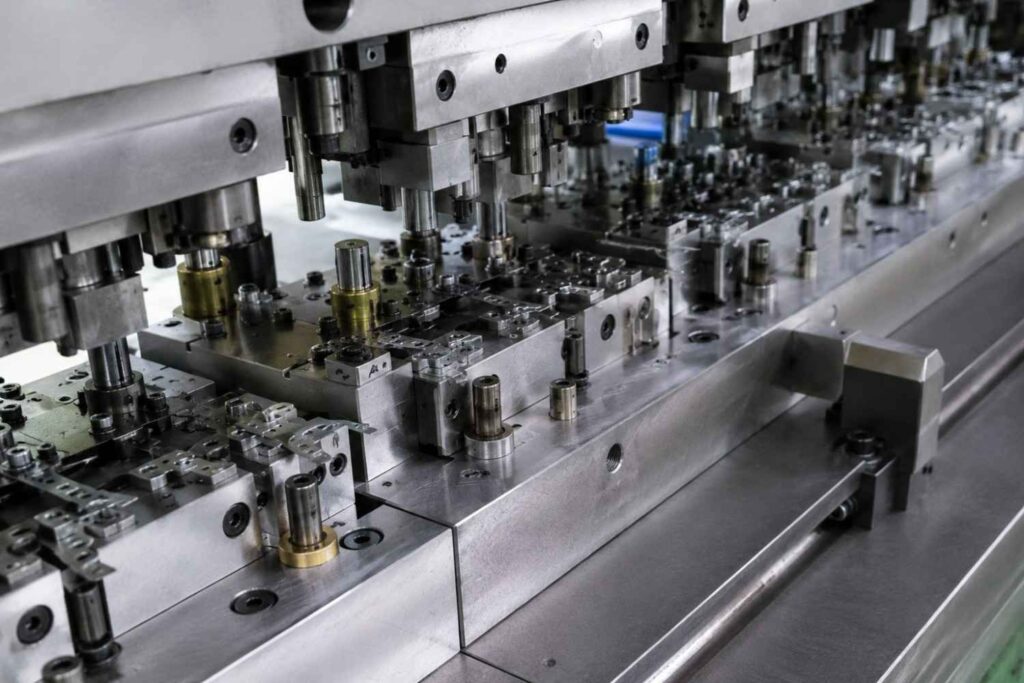
For the physical tool enquiry, compare stamping-die configurations against the clip geometry and access requirements. For stamping-die development and tryout, provide the formed drawing, strip specification, duty history and requested evidence package. Confirm the scope and available project records before relying on any proposed capability.
This application study is deliberately distinct from a flat-pattern calculation or a springback adjustment. Those reviews help define the formed geometry. The fatigue study asks whether the final component continues to meet its agreed function under the specified repeated duty, with its actual material and processing history documented.
Frequently asked questions
Can hardness or tensile strength alone establish stamped spring clip fatigue life?
No life prediction is established here. Supplier fatigue data has defined specimen and loading conditions, and the formed clip requires application-specific validation. The proposed plan retains material condition, geometry, process history and duty together.
Is 480°C for 1 hour a general spring-steel heat-treatment recipe?
No. The number cited here is Alleima’s guidance for its named 9RU10 grade and stated purpose. Obtain approval for the actual grade, incoming condition and part route before treatment. [2] Alleima.
Does a 30 N maximum define a complete fatigue test?
No. The hypothetical worksheet shows different amplitudes for 10–30 N and 0–30 N cycles. Also define the control variable, fixture, environment, frequency, target and inspection requirements.
Does a runout prove an infinite service life?
No. It records survival to a stated stopping count under the tested conditions, not fracture life or unlimited durability. Functional and force-retention requirements still need their own evaluation.
Did SSP test the clips in this article?
No. This is an illustrative application guide with no supplied SSP project or test records. The loads, matrix, cycle targets and retention example are teaching assumptions, not measured results.
Technical references
Reviewed on 3 November 2026. Grade-specific data and manufacturer guidance support the statements cited nearby. They do not validate the hypothetical clip, prescribe a universal process or establish SSP project outcomes.