Threaded insert pull-out strength is not a single catalog number. It is the axial load at which the installed insert, surrounding plastic, or another part of the joint can no longer retain the applied load. The result depends on the insert geometry, plastic grade and condition, boss design, molding or installation process, and the exact test method. Insert-supplier data are useful for screening, but final acceptance should come from tests on production-representative assemblies.
Engineering answer in brief
- Start with the joint load case, then convert it into an explicit axial proof-load requirement.
- Select the insert and boss together. Pull-out retention comes from plastic engaging the insert’s knurls, grooves, flanges, or undercuts.
- Verify the competing failure modes: axial pull-out, torque-out, boss cracking, screw or thread failure, and long-term relaxation.
- Use catalog values only to compare like-for-like options. Qualify the final resin, insert, mold, conditioning, assembly torque, and test fixture.
What threaded insert pull-out strength actually means
In an axial pull-out test, a tensile load is applied along the insert’s thread axis while the plastic part is supported by a fixture. The reported maximum load is meaningful only when the specimen geometry, support opening, screw engagement, loading rate, material condition, temperature, and failure definition are also recorded. SPIROL states that published insert performance data should be used as comparative guidance because manufacturers do not necessarily use consistent materials or test methods, and that final approval should be based on testing in the actual application. SPIROL, Performance Expectations for Threaded Inserts in Plastic Assemblies.
Pull-out is also only one part of joint performance. The insert must resist the installation and service torque needed by the bolted joint, while its axial retention must exceed the applicable tensile load. SPIROL’s design guide describes torque resistance as strongly related to insert diameter and pull-out resistance as strongly related to insert length, while noting that the two responses interact. SPIROL, Inserts for Plastics Design Guide, pp. 2-4.
For that reason, a design review should keep at least three requirements separate: the axial proof load, the permitted tightening torque, and durability after the expected environmental and assembly history. A specimen can pass a one-time pull test yet still be unsuitable if the boss cracks during installation, the insert rotates during tightening, or the plastic relaxes under sustained clamp load.
Illustrative load case for an injection-molded housing
Assume a cover is retained by several M4 screws engaging molded-in metal inserts in a plastic housing. For one critical insert location, the hypothetical mechanical analysis assigns a maximum axial service load of 250 N. The project team selects an illustrative design factor of 2.5 for its preliminary screen. This value is an assumption for the example, not a standard requirement.
Required axial proof load = maximum service load × selected design factor
625 N = 250 N × 2.5
The resulting 625 N is a minimum proof-load target for this example. It is not a predicted pull-out result and it does not prove adequate screw preload, fatigue life, impact performance, or long-term clamp retention. Those are separate checks. The load allocation should also be revisited if the cover can pry, if the load is eccentric, or if manufacturing tolerances allow one fastener to carry more than its nominal share.
| Input | Example value | How it should be treated |
|---|---|---|
| Thread size | M4 | Hypothetical packaging choice; confirm screw class, engagement, and insert drawing. |
| Peak axial service load at one insert | 250 N | Hypothetical structural-analysis output; replace with project load cases. |
| Preliminary design factor | 2.5 | Illustrative engineering assumption; obtain project approval. |
| Axial proof-load target | 625 N | Calculated from the two assumptions above. |
| Housing resin | Production PC grade, to be selected | Exact grade, colorant, regrind policy, and conditioning must be frozen before qualification. |
| Insert | Molded-in metal insert, supplier part not yet selected | Use the supplier’s drawing and application guidance; do not design from thread size alone. |
| Environment | Project-specific | Define temperature, moisture, chemicals, vibration, and number of assembly cycles. |
The table deliberately leaves the resin grade, insert series, and environment open. Filling those fields with real project data is part of the engineering work, not an editorial detail.
Using catalog data without turning it into a promise
PennEngineering publishes pull-out and torque-out results for specific insert series tested in ABS and polycarbonate. Its tables also state that mounting-hole size, material, and installation procedure affect results and recommend performance testing in the application. These values can help eliminate clearly unsuitable options, but they should not be copied into a drawing as a guaranteed housing capability. PennEngineering, SI Inserts for Plastics catalog, performance tables and notes.
A responsible screen compares candidates tested with the same material and method, then carries more than one promising option into component-level trials. SPIROL similarly cautions against comparing catalog data across manufacturers because the underlying methods and materials may differ. SPIROL, performance expectations guidance.
How insert retention is created
Insert retention comes from mechanical engagement between the plastic and the insert’s external features. Knurls resist rotation; grooves, barbs, flanges, and undercuts provide plastic shear area against axial movement. SPIROL recommends sectioning an installed insert to confirm that plastic has filled the retention features because incomplete flow reduces both torque and pull-out performance. SPIROL, Inserts for Plastics Design Guide, p. 3.
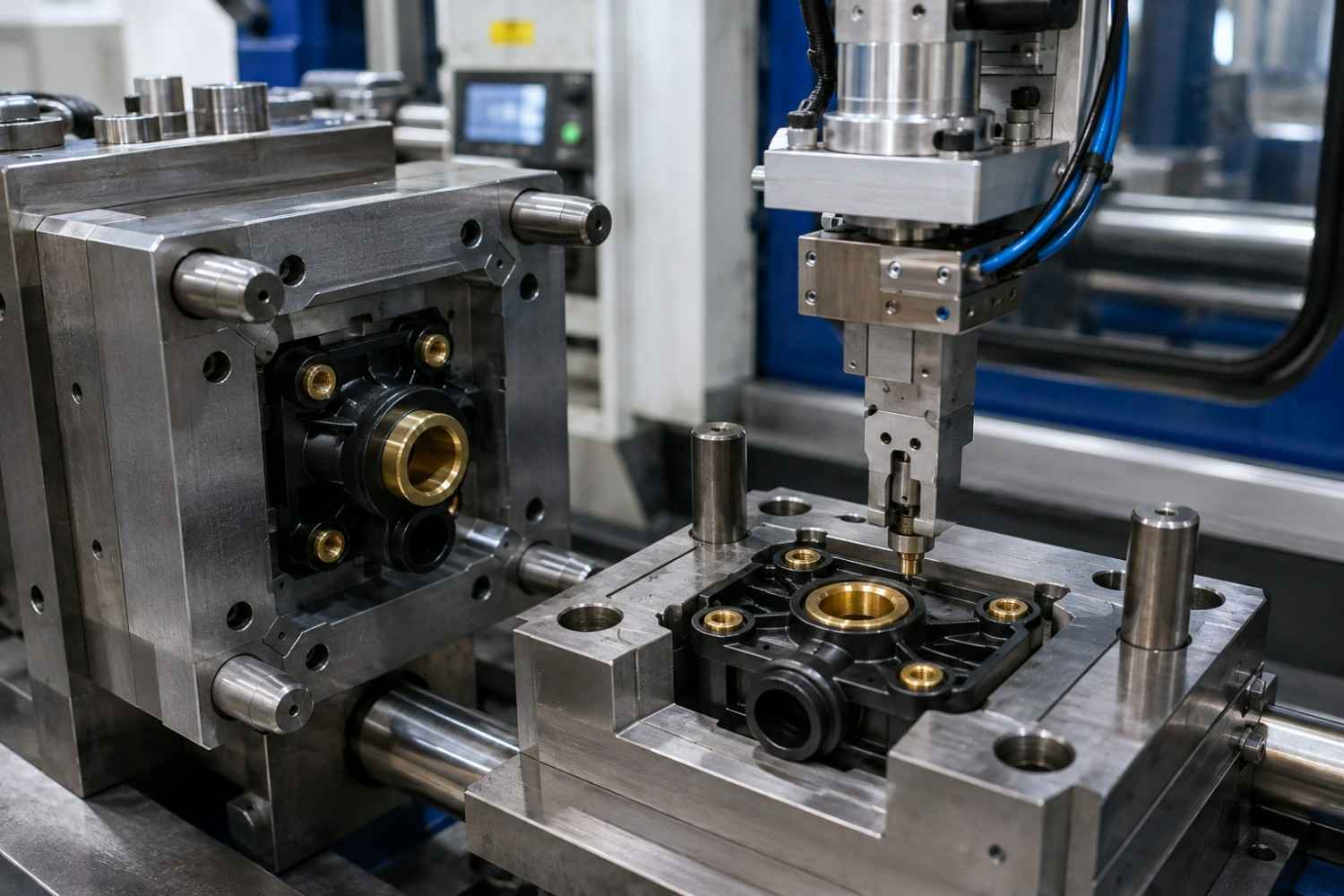
Molded-in inserts are positioned in the mold before plastic injection. This permits plastic to flow around the retention geometry; SPIROL describes molded-in designs as offering high torque and pull-out resistance, while Böllhoff describes axial retention from optimized flank overlap or a generated undercut in its molded-in insert families. SPIROL design guide, p. 7; Böllhoff, IMTEC molded inserts.
Post-mold heat or ultrasonic installation can be appropriate when the resin and assembly route suit it. The insert is driven into a correctly sized molded hole while the surrounding thermoplastic is softened or mobilized. SPIROL notes that the hole must provide enough plastic to fill the external features, and that oversize holes reduce performance while undersize holes can create undesirable stress and cracking. SPIROL, proper hole design for heat and ultrasonic inserts.
| Route | Where retention comes from | Key verification |
|---|---|---|
| Molded-in insert | Plastic flows around knurls, grooves, flanges, or undercuts during molding. | Insert location, perpendicularity, encapsulation, flash, contamination, and mold protection. |
| Heat or ultrasonic insert | Reflowed thermoplastic fills external retention features in a preformed hole. | Supplier hole geometry, installation depth, alignment, energy or temperature window, and section quality. |
| Press-in insert | Interference and insert features displace or engage the plastic. | Installation force, boss stress, cracking, pull-out, and suitability for the selected resin. |
This comparison does not declare one universal winner. The correct route depends on the resin, access, mold risk, volume, performance requirement, and insert supplier’s validated geometry.
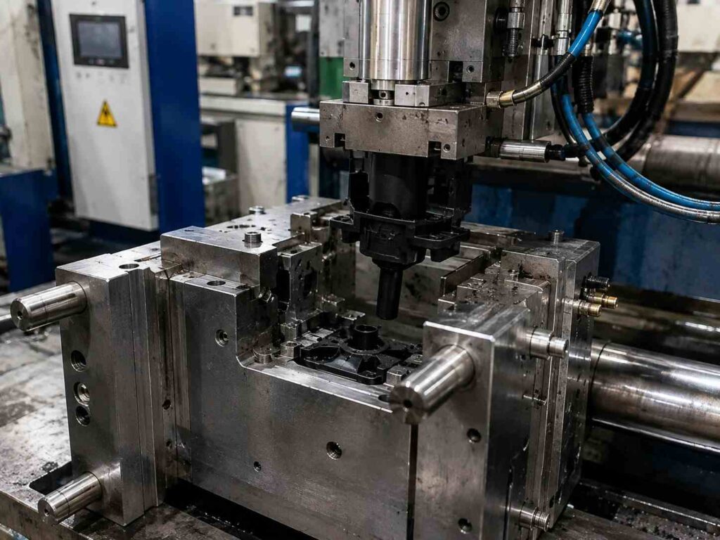
Boss, material, and molding decisions that change the result
Boss geometry
A boss must provide enough surrounding plastic to accept installation and service loads without splitting or excessive deformation. For heat and ultrasonic inserts, SPIROL gives a general boss-diameter guideline of two to three times the insert diameter, with the multiplier tending to decrease for larger inserts. The same source stresses that the insert supplier’s recommended hole size should be used and reviewed when fillers are present. This is supplier guidance for a specific installation family, not a universal rule for every molded-in insert. SPIROL, optimum hole-design guidelines.
For a molded-in design, the starting geometry should come from the selected insert drawing and mold concept. Check the resin flow path, knit-line location, local wall transitions, venting, core-pin support, and whether an insert can be loaded and retained repeatably without damaging the cavity. These are design-review items that must be resolved using the actual part and tool, not assumed from a generic boss ratio.
Resin grade and condition
“Polycarbonate” or “PBT” is not a complete material specification. Reinforcement, color package, recycled content, moisture condition, molding history, and temperature can change the local mechanical response. SPIROL explicitly lists plastic composition, fillers, component design, and processing among the variables that prevent universal insert-performance values. SPIROL, performance expectations guidance.
Time under load matters as well. Celanese’s polyester design manual explains that the viscoelastic behavior of plastics requires creep to be considered even at room temperature, and that actual assemblies vary with wall thickness, dimensions, and material properties. Therefore a short pull-out test should not be used as the only evidence for a joint that must retain clamp load for years. Celanese, Polyester Technical Manual, creep section.
Process and inspection
For molded-in inserts, define how the insert is seated, oriented, retained, and detected before injection. Then inspect location, height, perpendicularity, thread condition, flash, short shot, voids, and plastic fill around the retention features. Sectioning first-off or development parts is especially useful because it shows whether the plastic actually mirrors the external insert geometry, a check recommended in SPIROL’s design guide. SPIROL design guide, p. 3.
The injection mold must control insert positioning and protect the cavity from a misplaced insert, while the injection molding process must fill the boss consistently without moving the insert or leaving incomplete encapsulation. These two responsibilities should be reviewed separately even when one supplier supports both.
A production-representative pull-out test plan
The test should answer a decision, not merely generate a high number. For this illustration, the first decision is whether a candidate insert and boss can exceed the 625 N proof target without boss cracking, insert movement, or thread damage. The second is whether the result remains acceptable after the relevant environmental and assembly history.
- Freeze the specimen definition. Record resin manufacturer, grade, lot, colorant, reinforcement, permitted regrind, molding date, cavity, insert supplier and part number, screw, thread engagement, and conditioning.
- Define the fixture. Support the housing so the fixture does not reinforce the boss or crush nearby ribs. Align the tensile axis with the insert axis and document the support opening.
- Define the loading method. Specify the machine, load-cell range, crosshead or displacement rate, preload, data rate, and stop rule. If the insert supplier has a test method, reproduce it when comparing with that supplier’s data.
- Record more than peak load. Capture load-displacement behavior, first visible damage, peak load, displacement at the selected proof load, and the exact failure mode. Photographs and retained fracture surfaces make later diagnosis easier.
- Add conditioning that represents use. Create separate groups for the environmental exposures, aging, chemical contact, vibration, or repeated screw cycles that are credible for the product. Do not mix different histories into one unlabeled average.
- Set acceptance before testing. For the illustrative screen, every tested part must carry 625 N without the insert moving or the boss cracking. A real qualification plan also needs an approved sample size, statistical treatment, measurement uncertainty, and rules for invalid tests.
| Group | Purpose | Illustrative quantity | Evidence to retain |
|---|---|---|---|
| As-molded baseline | Establish initial distribution and failure mode. | 10 | Peak load, proof-load displacement, failure photos, cavity and lot. |
| Conditioned parts | Measure the effect of the project-defined temperature and moisture history. | 10 per condition | Condition record, mass or moisture evidence where relevant, same mechanical outputs. |
| Assembly cycling | Check damage from the specified removal and reinstallation sequence. | 10 | Torque history, thread inspection, pull-out result, failure mode. |
| Process-limit samples | Challenge approved molding or installation-window limits. | Defined by validation plan | Actual process records linked to each specimen. |
Ten specimens can reveal gross problems in an engineering screen, but it does not automatically establish a statistically justified production tolerance. The quality team should set the qualification quantity and confidence requirement for the product risk.
Read the failure mode, not only the load cell
| Observation | Likely mechanism to examine | Next evidence |
|---|---|---|
| Insert exits with a plug or cone of plastic | Axial shear or tensile failure through the surrounding resin. | Section the boss; compare engagement length, wall thickness, knit-line position, and material condition. |
| Insert pulls out cleanly with poorly replicated knurls | Incomplete plastic flow into the retention features. | Cross-section parts and review molding or installation parameters and hole geometry. |
| Boss splits during installation or test | Excessive interference, insufficient surrounding plastic, a sharp stress concentration, or brittle material condition. | Measure hole and boss geometry; inspect cracks before testing; review supplier hole guidance. |
| Insert rotates before axial failure | Torque retention is the controlling mode. | Run a defined torque-out test and inspect circumferential engagement. |
| Screw or internal thread fails first | The insert-to-plastic interface exceeded the strength of another joint element. | Check screw property, engagement, thread damage, and whether the test still answers the intended requirement. |
| Large displacement without a sharp peak | Progressive plastic deformation, fixture compliance, or slip. | Separate machine, fixture, and specimen displacement; add visual or extensometer measurement. |
These diagnoses are starting hypotheses, not automatic root-cause verdicts. Confirm them with sections, dimensions, process records, and repeat tests. The objective is to connect the measured load to a physical mechanism that the design or process team can control.
Release checklist for an insert-retained housing
| Decision item | Release evidence |
|---|---|
| Load case | Approved axial, torque, impact, fatigue, and sustained-load requirements with load paths documented. |
| Material | Exact resin grade and conditioning state, with permitted colorant and regrind rules. |
| Insert and screw | Controlled supplier part numbers, drawings, finish, screw property and thread engagement. |
| Boss and mold | Reviewed geometry, insert retention method, core-pin support, venting, and error detection. |
| Process | Qualified molding or installation window and traceable actual settings. |
| Inspection | Location, height, perpendicularity, thread condition, flash, cracks, and section criteria. |
| Mechanical verification | Predefined pull-out and torque-out methods, environmental groups, acceptance criteria, and failure records. |
| Production control | Sampling and reaction plan tied to the risks found during development. |
Frequently asked questions
What is a good threaded insert pull-out strength?
A good value is one that exceeds the approved application requirement with the required margin and after relevant conditioning. There is no universal number for an M4 or any other thread size because insert geometry, plastic, boss, processing, and test methods change the result. Application testing is the final basis for approval. SPIROL performance guidance.
Can a supplier catalog value be used as the design allowable?
Use catalog values to compare candidates only when the material, insert, and method are understood. PennEngineering and SPIROL both warn that material, hole or process variation affects performance and recommend testing the intended application. PennEngineering SI catalog; SPIROL performance guidance.
Does a longer insert always solve low pull-out strength?
Greater engagement length can increase available retention area, and SPIROL describes pull-out resistance as strongly related to length. It is not an automatic fix: boss geometry, resin failure, incomplete feature fill, insert diameter, torque requirements, and packaging can still control the result. SPIROL design guide, pp. 2-4.
Should pull-out be tested before or after environmental conditioning?
Both can be useful. Baseline tests show the initial distribution, while conditioned tests address the state in which the joint must operate. The conditions should come from the product environment and the selected resin’s behavior, not from a generic editorial recipe.
When should molded-in inserts be considered?
They are worth evaluating when the project needs strong retention, can position and protect the insert inside the tool, and can justify the tooling and process controls. SPIROL and Böllhoff describe molded-in families that use plastic flow around external features to generate pull-out and torque resistance. SPIROL design guide; Böllhoff IMTEC overview.
References
- SPIROL, Inserts for Plastics Design Guide.
- SPIROL, Performance Expectations for Threaded Inserts in Plastic Assemblies.
- SPIROL, How to Design the Proper Hole for Heat / Ultrasonic Inserts.
- PennEngineering, SI Inserts for Plastics.
- Böllhoff, IMTEC Thread Inserts for Plastics.
- Celanese, Polyester Technical Manual.