







Undercut injection molding side-action design starts with a release question: can the steel forming the feature withdraw completely before the part is ejected? Define the main draw direction, map the trapped features, compare geometry changes with moving tooling, and verify the entire release sequence. Protolabs describes side-actions as a way to withdraw the mold surfaces that would otherwise hold an undercut part. [1] Protolabs.
This application guide follows an illustrative enclosure with a side-facing recess and a separate internal latch. It develops a clearance budget, an idealized travel calculation and a practical approval record. It does not prescribe a mold mechanism, angle-pin size, permissible load or universal clearance for production.
Side-action review in brief
- Assign a release direction to each feature before choosing a mechanism.
- Separate the function that must remain from geometry that may change.
- Check the largest interference and available withdrawal throughout the motion.
- Distinguish actuation, closed-position support and open-position retention.
- Approve actual release and functional parts with documented trial evidence.
Map molded enclosure undercuts against their release directions
An undercut is a feature that obstructs withdrawal in the selected tooling arrangement. Protolabs contrasts straight-pull removal with features requiring the forming steel to move away before ejection. Its examples include side holes, slots and recesses. [1] Protolabs. A useful assessment therefore names the direction and steel involved, rather than simply marking every unusual surface “undercut.”
For this study, assume the enclosure opens along a main axis called Z. One exterior recess needs steel approaching along a lateral axis called X. An internal hook sits elsewhere in the enclosure. These axis names describe the teaching model, not an approved tool orientation. Treat the two features as separate release problems until the CAD review demonstrates otherwise.
Prepare a feature map with the relevant faces, functional purpose, proposed forming member and withdrawal direction. Identify which neighboring ribs, walls or inserts lie inside each member’s swept volume. Preserve views from the closed position through withdrawal and ejection, using consistent feature identities across the drawing and tool proposal.
Keep the internal hook’s service behavior in a separate record. A latch that deflects during assembly has not thereby been qualified to strip from a mold. The existing snap-fit design guide addresses assembly strain and force; this study addresses how the forming steel exits. Link the decisions without replacing one analysis with the other.
Compare geometry changes with moving tooling
Retain the function while reviewing the shape
Protolabs describes moving the parting line, using hand-loaded inserts, employing suitable bumpoffs and considering secondary operations as possible responses to undercuts. Which option is appropriate depends on the geometry and manufacturing plan. [2] Protolabs. Start the review by stating what may change: an opening position, a local wall, a cosmetic witness or the feature’s manufacturing route.
For the example side recess, ask whether an opening to an accessible edge would preserve the interface. For the internal hook, ask whether a pass-through opening is acceptable behind it. Do not approve either change merely because it simplifies tooling; return the modified geometry to the assembly, appearance and environmental requirements for a new decision.
Shutoffs are another possibility for suitable features. Protolabs illustrates opposing steel surfaces and pass-through cores forming holes and hooks in a straight-pull arrangement, and explains how sealing-face wear can lead to flash. [3] Protolabs. The review should identify the actual contact surfaces and what their witness or flash would mean to the product, rather than treating a shutoff as a cost-free substitute.
Keep the candidate mechanisms distinct
For an external feature with an accessible withdrawal path, a translating side-action is one concept to investigate. Do not assume that the same external slide reaches an internal reverse hook. A separate internal release concept, a removable insert or a geometry revision may need evaluation. Record the unresolved feature explicitly instead of hiding it in a generic “slides included” quotation.
A bumpoff relies on the molded material deforming past the feature. Protolabs calls for suitable flexibility and smooth, radiused geometry in its discussion; this is not permission to force every rigid enclosure over a sharp obstruction. [2] Protolabs. For the present hypothetical enclosure, leave stripping unapproved until the exact resin, release geometry and trial evidence support it.
For manual inserts or a post-molding operation, request a complete handling and inspection proposal. Compare the proposed workflow, feature accessibility and acceptance method with the product requirements. Do not invent a universal production-volume crossover or percentage cost saving. The useful output is a reviewable process concept and a comparable quotation.
Build a numerical clearance budget before choosing travel
Hypothetical inputs: Let u be the lateral overlap of forming steel that must clear the molded feature, measured along X. Assume u = 2.40 ± 0.10 mm. Choose an additional geometric allowance c = 0.50 mm solely for this teaching example. It is a design input for review, not a standard minimum or a claim that it covers every tolerance and operating effect.
| Review condition | Overlap u (mm) | Chosen allowance c (mm) | Required geometric withdrawal u + c (mm) |
|---|---|---|---|
| Smallest assumed overlap | 2.30 | 0.50 | 2.80 |
| Nominal assumed overlap | 2.40 | 0.50 | 2.90 |
| Largest assumed overlap | 2.50 | 0.50 | 3.00 |
The arithmetic is a direct sum: 2.50 + 0.50 = 3.00 mm at the largest assumed overlap. Use the upper-bound row for the following idealized motion screen. The lower row is not an alternative acceptance limit for the same design. A production calculation needs a defined dimensional chain and an agreed interpretation of the allowance.
Before applying that sum to a real tool, identify where each dimension begins and ends. A recess depth on the product drawing may not equal the complete steel interference along a proposed oblique path. Request a section and a swept-volume check showing that the selected displacement actually clears the surrounding part.
List the exclusions next to the result. This simple budget has not evaluated pin-to-hole clearance, intentional delay, thermal movement, wear, elastic deflection, part distortion or other nearby geometry. Do not silently spend the same allowance on several different effects. Assign separate evidence or a revised budget where the actual design requires it.
Check side-action travel with a defined angle convention
DME identifies angle pins and their inserts as components used to actuate sliding core blocks. It directs users to product-specific installation instructions and assigns fitting responsibilities to the moldmaker. [4] DME. A kinematic calculation helps frame the discussion, but it does not select or qualify those components.
Idealized model: Assume perpendicular X and Z axes, rigid members, continuous engagement and no lost motion. Let H be effective opening displacement along Z while the pin is actively driving the slide. Let θ be the angle of the pin from Z, not from the horizontal. The right-triangle relationship is S/H = tan θ, so lateral travel S = H tan θ. For target travel Sr, Hr = Sr/tan θ.
All angles and displacements in the next table are hypothetical comparison inputs. The equations are elementary geometry under the stated assumptions, not catalog travel ratings. In particular, H is not necessarily the machine’s entire mold-opening stroke.
| Assumed pin angle from Z, θ (degrees) | Effective opening required for 3.00 mm travel, Hr (mm) | Travel at assumed H = 9.00 mm, S (mm) | Geometric screen at H = 9.00 mm |
|---|---|---|---|
| 10 | 17.014 | 1.587 | Below the assumed target |
| 15 | 11.196 | 2.412 | Below the assumed target |
| 20 | 8.242 | 3.276 | Above the assumed target in this ideal model |
For the last row, 9.00 × tan(20°) = 3.275732 mm, rounded to 3.276 mm. The idealized excess over the target is about 0.276 mm. This is not an approved operating margin: it remains subject to the exclusions in the clearance budget and the actual mechanism’s engagement and motion.
The table does not establish that the larger angle is the better design. Request separate component and load review, including pin geometry, support, engagement and the moldmaker’s installation requirements. Keep the geometry result labeled as a motion screen so it cannot be mistaken for a strength or durability calculation.
Ask the tool designer to mark the displacement at which the slide first moves, the point where the feature is fully clear, the end of pin engagement and the permitted start of ejection. If there is delayed motion, calculate the effective driving displacement from the actual sequence. A machine opening number without those definitions is insufficient for this review.
Review actuation, support and retention through the complete sequence
DME distinguishes the slide retainer’s role in holding the slide withdrawn for ejection and subsequent pin re-entry from the heel block’s role in supporting the slide in the closed molding position. It also discusses slide weight and orientation when selecting retention. [5] DME. Do not use one component name as evidence that all these functions are covered.
Build the sequence review around actual tool states. In the closed state, request the forming position and support concept. During opening, show the transition that creates withdrawal. At ejection, demonstrate that the forming steel and other moving members are outside the relevant swept volumes. During closing, show how the slide is located for the pin to re-engage.
For each state, name the design evidence and the trial observation needed. A CAD animation is useful for explaining the intended movement, but keep it separate from observations of the finished tool. Record any unresolved stop, retention or synchronization issue before authorizing automatic operation.
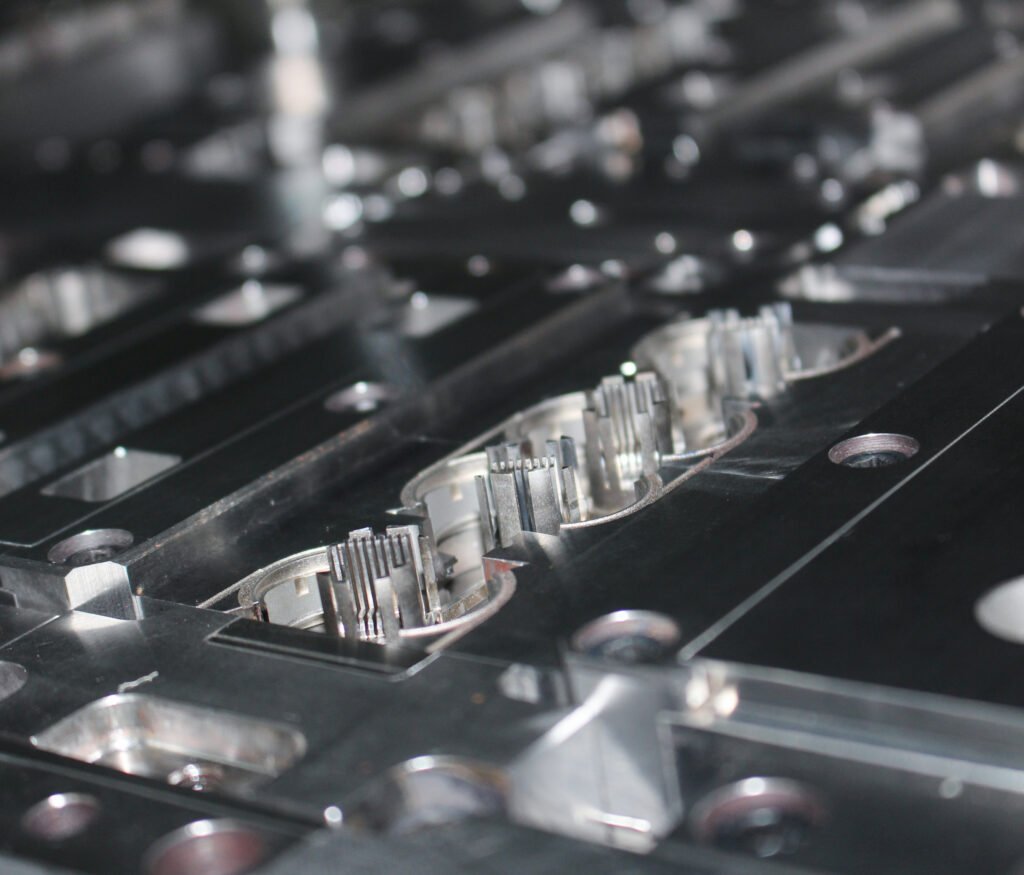
Review release surfaces in their own draw directions. The separate injection molding draft-angle guide covers taper and deep-feature release. Here, ask the moldmaker to identify the relevant surfaces and propose the feature-specific draft and finish, rather than assigning one angle to every face in the enclosure.
Document the interfaces that the side action must preserve
Turn the selected concept into a product-and-tool review package. Identify functional faces, assembly datums, allowable witness locations, cosmetic zones and the dimensions needing approval. Avoid treating the nominal CAD model as the entire acceptance definition. State how any local split or shutoff mark will be assessed on the finished component.
For the hypothetical exterior recess, request a section through the mating interface and a proposed inspection access direction. For the separate internal hook, identify the contact surface and clearance needed by its mating part. Neither requires invented universal tolerances; the product owner must define the actual functional limits.
Keep physical injection mold tooling configuration decisions distinct from the injection molding production and sample-approval scope. The tool proposal describes the release mechanism. The production agreement identifies the resin, sample state and product records required for acceptance. Reconcile both against the same drawing revision.
Plan inspection and release evidence before the first trial
The following checklist is a proposed approval workflow. Replace its open questions with project-specific acceptance criteria before a trial; it contains no measured outcomes or mandatory sample sizes.
| Decision | Evidence to review | Reason to keep approval open |
|---|---|---|
| Geometry can release | Feature map, tolerance budget and swept-volume review for every forming member | Only nominal travel or one isolated section has been checked |
| Tooling sequence is acceptable | Defined movement states, component instructions and supervised trial observations | Retention, clearance or pin re-entry remains unresolved |
| Molded interface is acceptable | Critical dimensions, witness condition and mating-part checks in specified sample conditions | Good release is being used as a substitute for fit approval |
| Repeat production may proceed | Approved process and inspection records, ownership of corrective actions and change-control requirements | Tool, resin or interface revisions lack a documented review |
Preserve part identities through the trial. Link observations to cavity, material lot, shot or sample identity and the tooling revision. Record release marks, local deformation and interface measurements using the agreed inspection method. If the result differs from the CAD expectation, retain both records and investigate the difference before modifying several variables together.
A useful next step is to send SSP Precision the enclosure CAD, drawing, exact resin and the function of each trapped feature for a project review. Request the proposed release directions, travel definitions, sample evidence and unresolved assumptions. Confirm the actual supply scope without assuming a particular actuator brand, mechanism or validated capability.
Frequently asked questions
Does every side opening need a side action?
No. Suitable holes or hooks can sometimes be formed with pass-through cores and shutoffs. Review the forming surfaces and product geometry before choosing moving tooling. [3] Protolabs.
Is the travel equation enough to approve an angle pin?
No. The idealized relationship only estimates displacement under explicit assumptions. DME directs users to product installation instructions and moldmaker fitting; component selection and load review remain separate. [4] DME.
Can the enclosure simply flex past its undercut?
Only treat that as a candidate requiring material and geometry evidence. Protolabs’ bumpoff guidance depends on appropriate flexibility and feature shape; it is not a universal release method for rigid housings. [2] Protolabs.
What is the difference between a retainer and a heel block?
DME describes retention of the withdrawn slide for ejection and re-entry, while heel blocks support its closed molding position. The design review must identify both functions. [5] DME.
Does this study demonstrate an SSP customer result?
No. The geometry, clearance budget and motion table are hypothetical teaching examples. No tool was built or tested for this study, and the existing photos are contextual only.
References and engineering limits
Primary manufacturer references were reviewed on 26 October 2026. Their process descriptions support the attributed concepts; supplier-specific product limits have not been represented as SSP capabilities. The numerical examples and approval worksheets are original illustrative material. Final geometry, mechanism and acceptance require project-specific review.