Injection molding rib design balances a useful load path with a thin, releasable and verifiable molded section. Start with the part’s deflection requirement and exact resin, then review rib base thickness, height, root transitions, draft and intersections together. Ribs can reinforce a wall without thickening the entire panel, but excess material at their junctions can create sink on the opposite face. [1] Protolabs.
This guide develops a drawing-review method for structural ribs. It is not a general troubleshooting guide, a screw-boss specification or a guarantee of molded performance. The numerical example is an original, idealized geometry calculation, not an SSP test or an approved production design. Recommendations below are proposed engineering review practices unless specifically attributed to a source.
Engineering answer in brief
- Define the load, supports, allowed movement and service condition before choosing a rib pattern.
- Identify which wall a thickness ratio refers to and where the rib thickness is measured.
- Use supplier guidance as a starting point, not a universal acceptance standard.
- Inspect the whole root and every crossing rather than approving isolated ribs.
- Release geometry only after structural, molding and appearance requirements have evidence.
Define the structural job before drawing a rib network
A useful first deliverable is a marked assembly section, not a list of preferred rib dimensions. Show where the load enters, which features support the part and which surface must remain within a functional envelope. State whether the concern is temporary movement, residual deformation, cracking, assembly interference or an unacceptable visible mark. These are separate acceptance questions.
For example, a proposed cover review might ask whether a specified load at its center causes contact with an internal component. The design owner should provide the load application area, support arrangement and allowable displacement. Without those inputs, an attractive rib pattern cannot be evaluated against the intended function. Do not silently substitute a hand squeeze for a defined component test.
Prepare a candidate-comparison sheet before modifying the model. Hold the assembly, resin revision and evaluation condition constant, or clearly identify changes. Compare a simpler rib arrangement against the existing design and explain why each rib is present. If a rib is intended only for location rather than reinforcement, name that function separately so the inspection plan does not confuse it with a structural requirement.
| Design input | Question to resolve | Proposed record |
|---|---|---|
| Load and support | Where is force applied and what restrains the part? | Assembly section and load-case definition |
| Functional movement | Which gap or alignment must remain acceptable? | Allowed displacement and measurement location |
| Material and condition | Which grade and service state are being evaluated? | Material revision and agreed evaluation conditions |
| Visible surfaces | Where would a rib witness be unacceptable? | Cosmetic-zone map and approval method |
| Production acceptance | What will be inspected on molded parts? | Dimension, appearance and functional evidence matrix |
Original planning worksheet. No loads, tolerances or sample quantities are prescribed.
Injection molding rib design: interpret thickness guidance in context
Protolabs recommends ribs and gussets no thicker than 60% of the nominal wall in its strength-design guidance. INEOS gives a different, polypropylene-specific sink-control example: a rib base no more than half the attached wall thickness and a height no more than 1.5 times that wall thickness. These are differently scoped supplier recommendations, not conflicting universal standards. [1] Protolabs; [2] INEOS.
Define W as the local reinforced wall thickness and b as the specified rib base thickness. The ratio is b/W. Record whether the drawing dimension refers to the straight rib section above its root transition or another defined measurement location. A dimension and its reference section must travel together; otherwise two reviewers can report different ratios from the same CAD model.
As an arithmetic illustration, a hypothetical 2.00 mm wall with a 1.00 mm rib base gives b/W = 0.50. A 1.20 mm base gives 0.60. Neither calculation establishes fillability, appearance or strength. They only show the relationship between two stated dimensions. Do not select 1.20 mm merely because it matches the largest value found in a general guide.
| Published guidance | Scope | How to use it |
|---|---|---|
| Protolabs: rib/gusset thickness at most 60% of nominal wall | Its general molded-part strength guidance | Starting design comparison, not a guaranteed appearance result |
| INEOS: base at most 0.5W and height at most 1.5W | Polypropylene guide’s sink-mark discussion | Review within the intended material and application context |
| Project-specific approved geometry | Actual resin, surface and tool configuration | Requires supplier review and representative part evidence |
For a new design, ask the selected resin supplier and moldmaker which starting guidance they support, and retain that answer. If the proposal falls outside their advice, record the reason and the additional evidence required. A deviation can be an engineering question rather than an automatic failure, but it should not disappear from the release record.
Review height, roots and intersections as one geometry
Do not inspect only the straight rib wall
Basilius explains that the mold cools the plastic from its exterior inward and that a rib-to-wall connection can create a locally thicker region. Its examples reduce rib thickness and root radii to address the risk of a visible sink on the opposite surface. [3] Basilius. The practical review implication is to take a section through the actual connection, not only through the rib’s free-standing middle.
My recommended CAD review includes the root, end termination, junction with a boss and crossing with another rib. Flag each location where several features converge and ask whether the combined section still matches the intended design basis. A grid should not receive approval simply because every isolated rib has the same nominal thickness.
Balance root transitions with local material accumulation
Protolabs describes fillets as a way to reduce stress concentration at sharp connections, while warning that an oversized fillet can introduce excessive thickness and sink. [1] Protolabs. Therefore, do not remove every root radius to improve a thickness plot, or enlarge every radius without reviewing the resulting section.
The proposed drawing record should identify the root geometry and the controlled visible face. Ask the structural reviewer to explain the transition, and the moldmaker to review its local moldability. If a compromise remains unresolved, compare alternative layouts rather than treating a single radius as independently responsible for every requirement.
Make height and spacing reviewable
Height should be measured from a defined wall surface and related to a specified pull direction. Record spacing as a clear distance or a center distance explicitly. Include the neighboring wall, boss and assembly keep-out zones in the review model. These definitions avoid an approval based on dimensions measured from different references.
For a candidate with many ribs, request sections through the spaces between them as well as through the plastic. Ask how the mold features will be made, inspected, cooled and maintained. This is a tooling-review question, not a claim that a universal minimum spacing applies to every resin, mold steel or machining method.
A hypothetical section calculation: why material location matters
Consider an idealized T-section with a horizontal plate 20 mm wide and 2 mm thick, plus one central rectangular rib 1 mm thick and 3 mm high above the plate. All dimensions are hypothetical. Ignore draft, root radii, shrinkage and tolerances. The two rectangles meet without overlapping. This is a geometry lesson, not a manufacturability approval.
Measure y upward from the plate’s bottom. The plate area A1 is 20 × 2 = 40 mm² with centroid y1 = 1 mm. The rib area A2 is 1 × 3 = 3 mm² with centroid y2 = 2 + 3/2 = 3.5 mm. The combined centroid is (40 × 1 + 3 × 3.5)/43 = 1.17442 mm.
The area second moment about the horizontal centroidal axis is obtained by adding each rectangle’s centroidal second moment and its area multiplied by the squared centroid offset. The rectangular formula b h³/12 follows from integrating y² across its area; the offset term follows by expanding the same integral about the combined centroid. This derivation concerns geometry only.
+ 1 × 3³/12 + 3 × (3.5 − 1.17442)²
= 33.02519 mm⁴
| Hypothetical section | Area | Centroidal I about the stated axis |
|---|---|---|
| 20 × 2 mm plate alone | 40 mm² | 13.33333 mm⁴ |
| Plate plus 1 × 3 mm rib | 43 mm² | 33.02519 mm⁴ |
| Equal-area flat plate, 20 × 2.15 mm | 43 mm² | 16.56396 mm⁴ |
The ribbed section has approximately 1.994 times the I of the equal-area flat section about this particular axis. That is not a measured part-stiffness improvement. It shows how the same area can be arranged differently. No load capacity, fatigue life, impact resistance or production benefit has been calculated.
For a real component, the proposed next step is an appropriate structural evaluation using its full geometry, material model, restraints and conditions. Include draft and root transitions rather than evaluating an ideal T-section and then releasing a different shape. If the part’s controlling requirement is in another direction, this single-axis calculation does not answer it.
Review release, filling and the physical tool together
Draft assists release, but Protolabs emphasizes that one angle does not suit every design. [4] Protolabs. Specify the pull direction and review taper across the complete rib height. Use SSP’s separate draft-angle guide for deep and textured features for the detailed release discussion; this article’s focus is the overall rib decision.
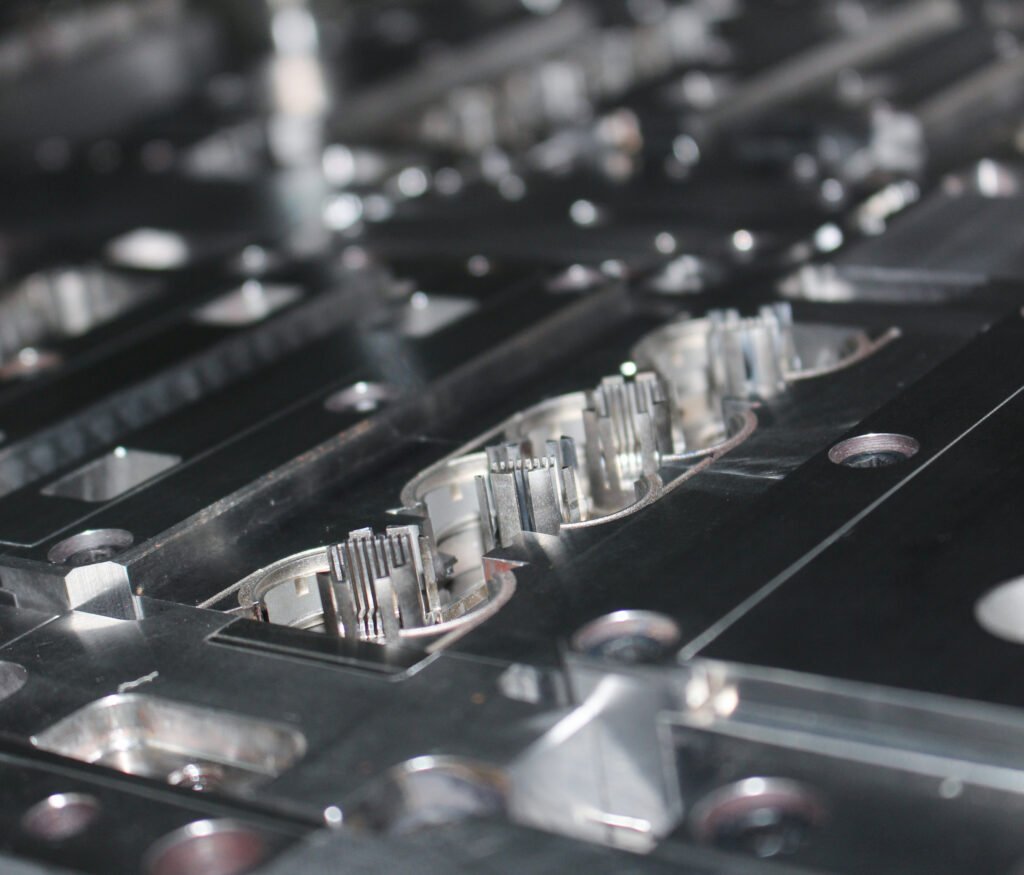
The recommended mold review should show which tool features form the rib sides, root and tip. Mark restricted ejection contacts and any functional surface where a witness would interfere with assembly. For the physical tool discussion, SSP’s injection mold tooling options provide a relevant starting point. Confirm the proposed configuration for the actual order rather than assuming this guide proves availability.
Autodesk identifies flow-front trapping, hesitation in thin regions, preferential flow in thicker regions and inadequate venting as possible contributors to air traps. Its guidance also warns that changing one aspect can introduce another problem. [5] Autodesk. A rib-layout review should therefore include the proposed filling pattern and air-escape strategy, not only a structural model.
Ask the molding reviewer to identify assumptions about gate position, feed arrangement and material. Record predicted concerns separately from trial observations. For gate-placement decisions, refer to the gate design and location guide. Detailed deep-rib burn-mark diagnosis belongs in its own application study, not a generic instruction to increase pressure here.
Turn a promising CAD model into a validation record
The following is a proposed evidence plan, not a standardized qualification sequence. Assign an owner and acceptance method to each line before sampling. Do not replace a missing structural result with a good-looking sample, or replace an unresolved appearance issue with a dimensional report that never examined it.
| Requirement | Proposed evidence | Boundary to record |
|---|---|---|
| Structural function | Approved analysis and relevant component test | Loads, supports, material and evaluation condition |
| Rib geometry | Measured bases, heights and root/assembly interfaces | Datum, method, cavity and part identity |
| Appearance | Controlled inspection of the face opposite the ribs | Viewing condition and approved acceptance sample |
| Complete molding | Traceable trial observations and inspection results | Material, tool and process revisions |
| Release decision | Closed evidence matrix with unresolved items visible | Approval owner and change-control triggers |
For an apparent failure, retain the raw observation before changing the design. Identify whether it is movement under load, local damage, incomplete molding, a visible depression or an assembly conflict. Then state the proposed corrective hypothesis and the requirement to be rechecked. This keeps an unrelated improvement from being reported as proof that the original problem has been solved.
Once the physical mold and evidence requirements are agreed, SSP’s plastic-part production services are the separate manufacturing enquiry route. Provide the drawing, exact resin and acceptance plan together. This guide does not establish a tolerance, test capability or material qualification for an individual SSP order.
Plastic rib design guidelines: drawing-release checklist
- Identify the structural function, load direction, supports and allowable movement.
- Specify the material revision and relevant evaluation conditions.
- Define wall thickness, rib base measurement, height and spacing references.
- Retain the source and scope of starting dimensional guidance.
- Section roots, ends, crossings and connections to other features.
- Review draft and tooling access in the intended pull direction.
- Compare filling and venting assumptions with the complete model.
- Mark visible surfaces and assembly keep-out zones.
- Assign structural, dimensional and appearance evidence separately.
- Record approved revisions and the changes that require re-review.
For orientation to both tooling families, see SSP Precision’s stamping and molding overview. A useful next-step request includes a marked assembly section and explicit acceptance questions, rather than asking for one supposedly correct rib ratio.
Frequently asked questions
What rib thickness should be used in injection molding?
There is no universal ratio. Use material-appropriate supplier guidance with a defined reference section, then obtain application-specific approval rather than treating a rule of thumb as evidence. [1] Protolabs; [2] INEOS.
Does adding more ribs automatically make a better part?
No such conclusion follows from rib count. The recommended review asks what each rib contributes to the defined load case and whether the complete layout satisfies geometry, molding, appearance and assembly requirements.
How high can a plastic rib be?
There is no universal limit in this guide. INEOS presents a 1.5-times-wall height in a polypropylene sink-control context. A different design needs its own material, tooling and validation review, not a height copied without its scope. [2] INEOS.
Why can a rib produce a mark on the opposite face?
Basilius explains that the connection can create a locally thick region whose cooling and shrinkage create a sink risk on the show side. Review that full junction and the actual surface acceptance requirement. [3] Basilius.
Does the T-section example prove the part is twice as stiff?
No. It compares the geometric second moment of two hypothetical sections about one stated axis. It omits the actual component’s material response, supports, load path and molded geometry. Use it as a screening lesson, not a production performance claim.
Technical references and scope
These public manufacturer and software-documentation sources support the attributed technical principles. Their dimensional advice is not an SSP capability statement or a universal standard. The checklists, review workflow and hypothetical section arithmetic are original engineering teaching aids.