






Specify sheet metal grain direction on the flat blank as an angle between the mill rolling axis and the axis of a named bend. Carry that same orientation into the nesting file, strip layout and first-article record. For a bend-sensitive grade, confirm the allowable orientation and radius with the material supplier before the tooling layout is released.
For a tooling or supplier-quality review, the practical question is whether a proposed rotation leaves each critical bend in an approved orientation. Start with the released part drawing. Then trace sheet metal grain direction through the raw material, blank and finished part.
Define sheet metal grain direction and the bend axis
Here, sheet metal grain direction means the mill rolling axis as tracked in a piece of rolled stock. SSAB explains that deformation during rolling can leave a directional microstructure. Its bending guidance shows why some products need different tool radii when the bend axis is aligned with or across that direction. See the SSAB workpiece setup recommendations.
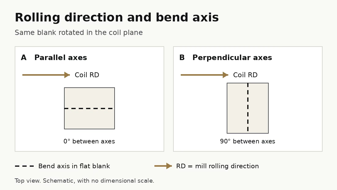
First, sketch the stock from above. Label the material arrow as rolling direction and mark the bend line as the axis around which the flange turns. In this article, parallel means 0° between those two axes and perpendicular means 90°. The angles describe the flat blank. The finished angle between the flange and its mating face is a separate dimension.
For a progressive tool, keep the stock feed arrow visible too. A design reviewer needs to know how the blank lies within the feed path and where its critical bend sits on that blank. For instance, once the supplier has identified sheet metal grain direction on the incoming stock, carry the mark through slitting or blanking in the layout record.
Read the rolling direction row in the supplier data
Next, match the material grade, product form, thickness band and setup conditions to the supplier data. When you evaluate sheet metal grain direction, copy the table’s definition of the tool radius into the review. SSAB distinguishes punch nose radius Rp from final inside part radius Ri where both are provided.
For example, the SSAB Hardox bending guarantee lists different punch-radius ratios for the two axes in its Class A row for Hardox 450 sheet at 2 ≤ t < 4 mm. The published conditions use dies with rolls, no lubrication and a single-step bend evaluated at 90° after unloading.
At an illustrative nominal thickness of 3.00 mm, multiply the listed ratio Rp/t by the thickness t. This gives the punch-radius figures below. The orientation decision changes the published setup threshold for that product and band by 3.00 mm.
| Bend axis to mill rolling axis | Published minimum Rp/t | Calculated minimum punch radius | Check for an illustrative 10.00 mm punch |
|---|---|---|---|
| Perpendicular, 90° | 3.0 | 3.0 × 3.00 = 9.00 mm | 1.00 mm above threshold |
| Parallel, 0° | 4.0 | 4.0 × 3.00 = 12.00 mm | 2.00 mm below threshold |
For both orientations, SSAB lists a die-opening guideline of W/t = 12 for this row, equivalent to 36.00 mm at the assumed thickness. If the applicable setup or thickness band changes, check the source again. These figures describe the specified Hardox product and supplier conditions. For a production stamping setup, review sheet metal grain direction with the actual material and tool geometry.
In particular, treat an oblique layout as its own condition if the supplier only publishes values for the two principal axes. Ask the mill or supplier how to evaluate the angle. For sheet metal grain direction on a part with two critical bends, identify the angle for each before selecting tooling.
Carry the orientation from the drawing into the nest
To decide how to specify rolling direction on a drawing, start with a flat view, a named reference edge and a critical bend ID. The NPTEL design-for-sheet-metal lecture recommends showing grain direction on the part drawing where it affects design. Tie your callout to geometry that the tooling and inspection teams can identify.
Anchor the bend line to a named feature
For example, an illustrative note could read, “Mill RD parallel to edge A in flat view. Axis B1 perpendicular to RD. Obtain drawing approval before rotating this orientation.” If the design allows angular variation in sheet metal grain direction, state the approved band and the drawing owner’s acceptance method.
For example, a prototype shop could start with individual cut blanks while a production supplier starts with a coil. If both make parts to the same drawing, ask each supplier to show where the same sheet metal grain direction is recorded. Use the part revision as the common reference.
Then label the flat file and the controlled drawing with the same revision. When a nesting change moves a bend line relative to the stock, measure the angle again in the flat view. As a drawing convention, keep sheet metal grain direction and any cosmetic brush pattern as separate callouts, each tied to its own purpose and reference.
Before committing to a strip layout, check every proposed orientation against the callout. For example, a half turn in the plane preserves the angle between two undirected axes. A quarter turn changes the orientation relative to each named bend. Use that geometric check when comparing carrier and blank placements for stamping die configurations.
If two bends have perpendicular axes in the flat blank, setting one perpendicular to the stock axis makes the other parallel. In that situation, compare the actual radii and functional priorities. If both bends need more room for forming, take the design back to the material and tooling teams before freezing the nest.
Verify the production orientation before release
During tryout, connect the drawing requirement to an identifiable sample. Use a sample ID, source stock ID and a marked blank or controlled image of the nest. The first-article record for sheet metal grain direction should connect the observed bend to the approved orientation and tool setup.
| Review point | Evidence to retain | What requires review |
|---|---|---|
| Incoming stock | Grade, condition, thickness, supplier lot and rolling-axis identification | Axis lost on a cut sheet or conflicting lot paperwork |
| Blank and layout | Drawing revision, approved nest or strip image, bend IDs and angles to the marked axis | Rotation outside the released layout or undocumented material orientation |
| Formed sample | Linked sample ID, tooling setup, observed outside bend surface and formed dimensions | Cracks, localized damage, dimensional departures or uncertain sample trace |
| Release and change | Drawing authority decision and the trigger for renewed verification | Changed grade, thickness, orientation, tooling or cutting route |
For an orientation comparison, hold grade, lot, thickness, edge preparation and tool setup constant as far as practical. Record any unavoidable differences. Then compare the same features under the agreed inspection method, especially the outside radius and the formed edges where the bend ends. The engineering team should set defect and dimensional criteria before it reviews results.
If the edge condition changed along with sheet metal grain direction, repeat the comparison with matched edges before assigning cause. Separately, if the bend is intact but the angle differs from the drawing, record the unloaded angle and review springback in metal stamping as its own issue.
For a mixed trial, tag every orientation group before forming. If a sample comes back without its material or orientation record, exclude it from the comparison. Include an example showing how to recover the rolling direction from the approved nest and stock record.
Likewise, separate two release decisions when the nest changes. First, verify that sheet metal grain direction still meets the drawing. Second, review the forming and dimensional evidence from the new layout. Document which evidence each decision relies on.
For the handoff, give the material buyer and die builder the same drawing note. An engineering team reviewing coil orientation for stamping can attach the supplier reference, the nest and the agreed checks to the stamping die development and tryout package. Include the permitted blank rotations in the release decision.
If a supplier asks how to specify rolling direction on a drawing, send the annotated flat view with one permitted example and one example that needs review. SSP Precision lists stamping tooling among its offerings. Use the marked drawing and material requirements when starting a tooling discussion.
Key takeaways
- Define sheet metal grain direction with a marked stock axis and a named bend in the flat view.
- Compare the correct material and radius definitions before approving the orientation.
- Release the drawing, nest and inspection record together so a later change is traceable.
Frequently asked questions
Does coil orientation for stamping have to be fixed for every part?
Fix sheet metal grain direction when it affects a drawing requirement, a supplier limit or a validated process. If trials support multiple layouts, list the approved orientations and the evidence for each.
Can the outside bend surface show which way the sheet was rolled?
For acceptance, verify sheet metal grain direction using the supplier’s material identification and a traceable record from stock to blank. A finished surface can carry processing marks. Use the surface inspection to assess the part condition.
Does a perpendicular bend axis always allow a smaller punch radius?
Use the material supplier’s values for both directions. Some product and thickness bands permit the same radius in both directions, so the grade, product form and setup determine the applicable limit.