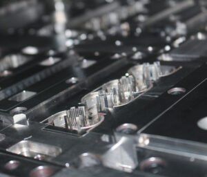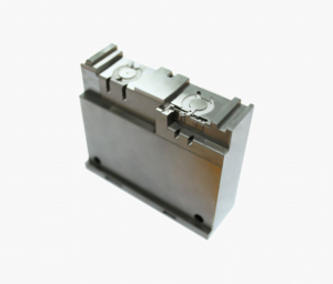
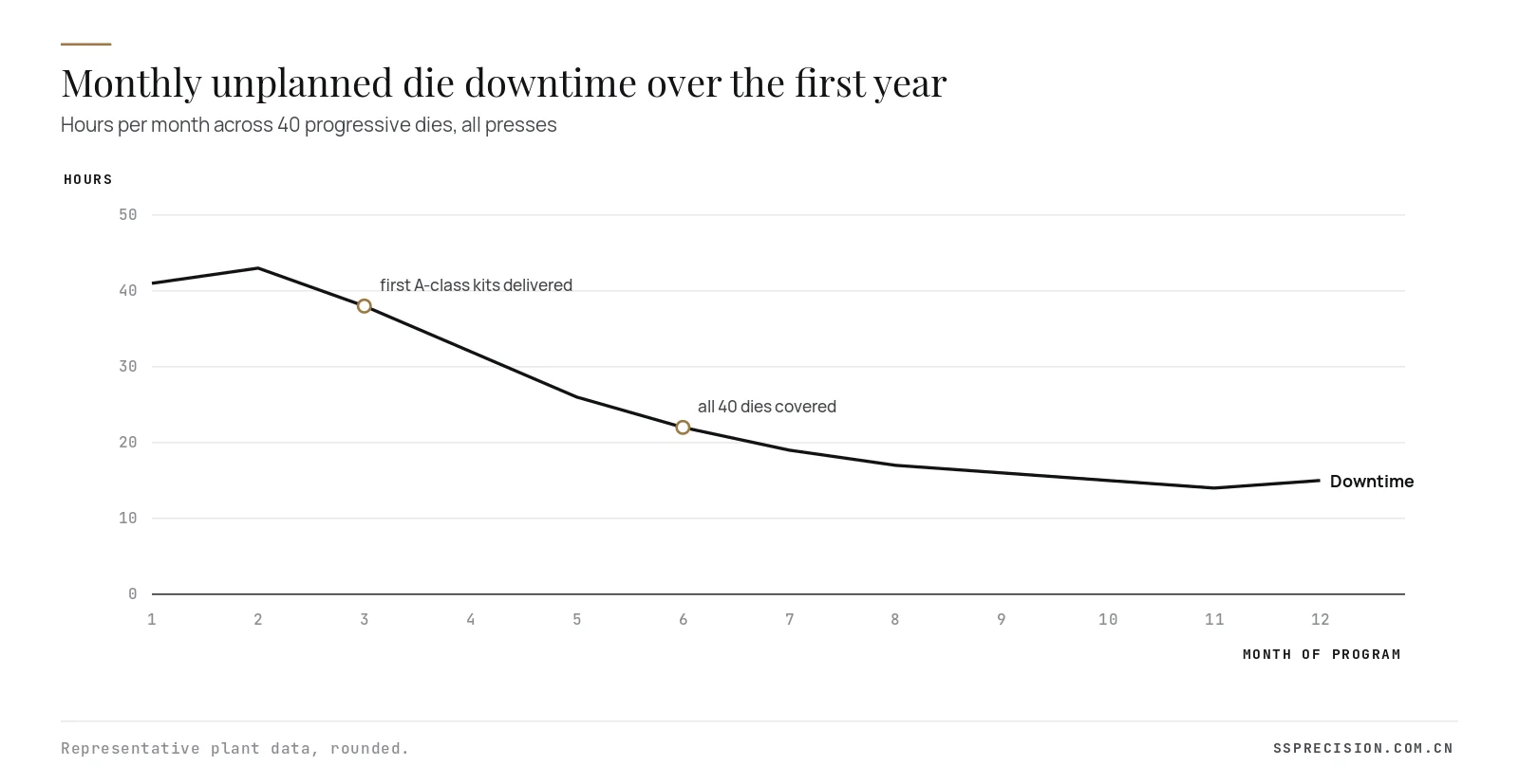
This die spare parts case study is about the most expensive part in a stamping plant: the one that is not on the shelf when a punch breaks. A metal stamping plant running 40 progressive dies from several toolmakers was losing more than 40 press hours a month to die breakdowns, most of it spent waiting for replacement components. Over one year, a structured die spare parts program with SSP cut unplanned die downtime by 63%.
- Customer
- Contract metal stamper for appliance and electrical OEMs
- Tooling
- 40 progressive dies from six toolmakers, 5 to 15 years old
- Presses
- 14 presses, 60 to 300 t, two shifts
- Parts covered
- About 1,150 wear components: punches, buttons, inserts, pilots, lifters
- SSP scope
- Audit, reverse engineering, drawings, spares manufacture, replenishment
- Program length
- First kits in 10 weeks, all dies covered in 6 months
- Delivery
- Shelf kits plus 72-hour express for critical parts
- Tolerance standard
- Interchangeable to ±0.005 mm on working profiles
The problem: good dies, no die spare parts
The plant’s dies were not bad. Most were well built and still produced good parts. The trouble came when something broke. A chipped piercing punch or a cracked die button stopped the press, and the maintenance team then had to find the original drawing, if it existed, identify the toolmaker, request a quote and wait. Local toolrooms could make a replacement in one to three weeks, often by measuring the broken part and fitting the new one by hand. Some original toolmakers had closed. For several dies there were no drawings at all.
To keep customers supplied, the plant ran overtime on other presses, shipped parts by air and sometimes ran a die with a missing station and a manual secondary operation. The maintenance manager estimated that waiting for die spare parts accounted for more than half of all unplanned die downtime.
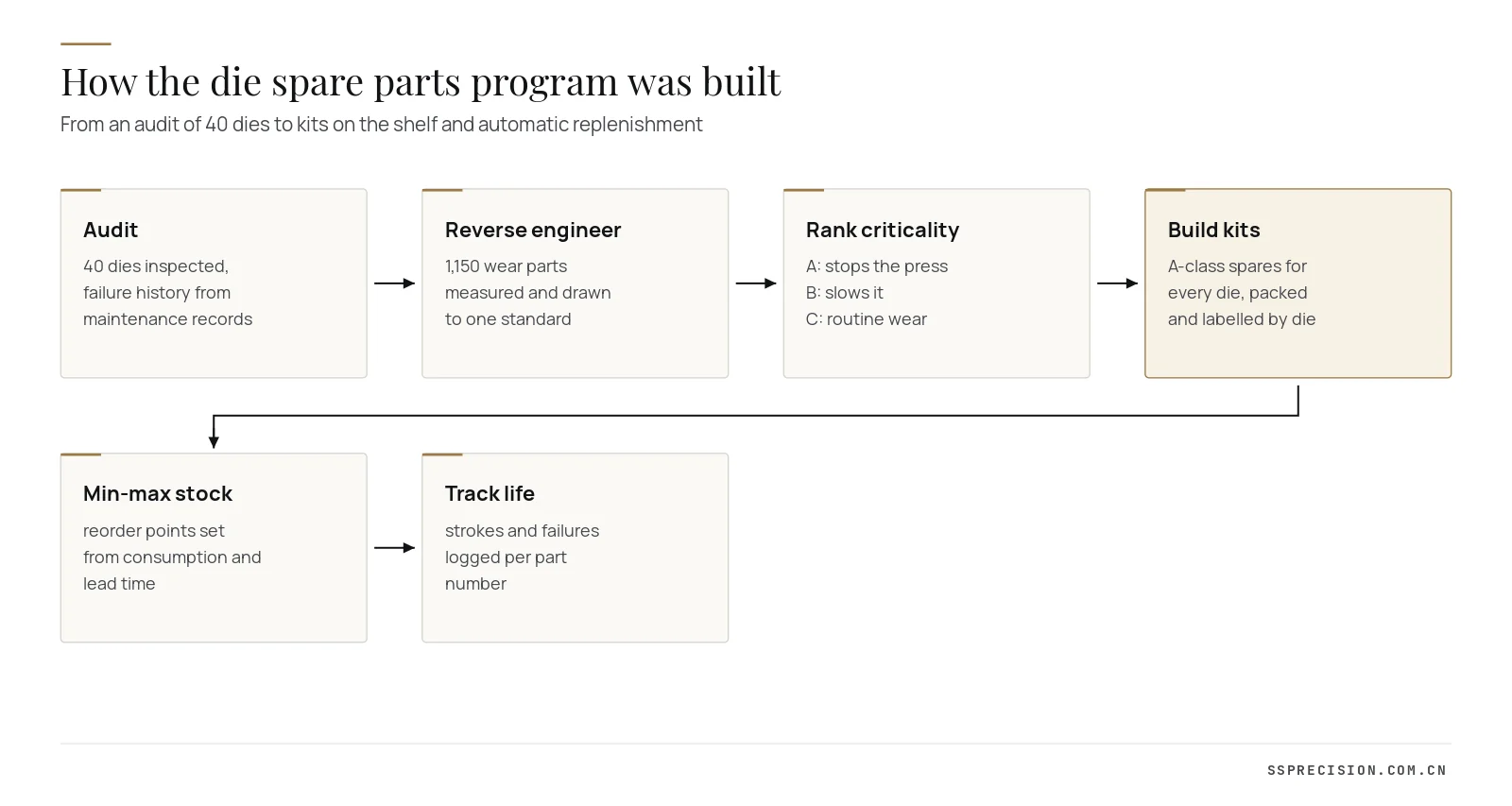
Step one: audit the dies and the failure history
We began with two weeks on site. Every die was opened, photographed and inspected, and its components were listed station by station. We combined that with two years of the plant’s maintenance records to see which components actually failed, how often and how long each failure had stopped the press. The pattern was clear: about 12% of components caused almost 80% of the downtime. Piercing punches in thin stainless and high strength steel, die buttons at heavily loaded stations, pilots and a handful of forming inserts were the repeat offenders.
Step two: reverse engineering and one drawing standard
A spare only saves time if it fits without fitting. That requires a drawing with the right tolerances, and for many components no such drawing existed. We measured about 1,150 wear components from the 40 dies, using the least worn examples and the mating features in the die as references, and drew each to a single standard: working profile, fit to the retainer, length and regrind allowance, material, hardness and surface treatment. Where two dies used nearly identical parts, we proposed a common part number, which reduced the number of unique die spare parts by about 15%.
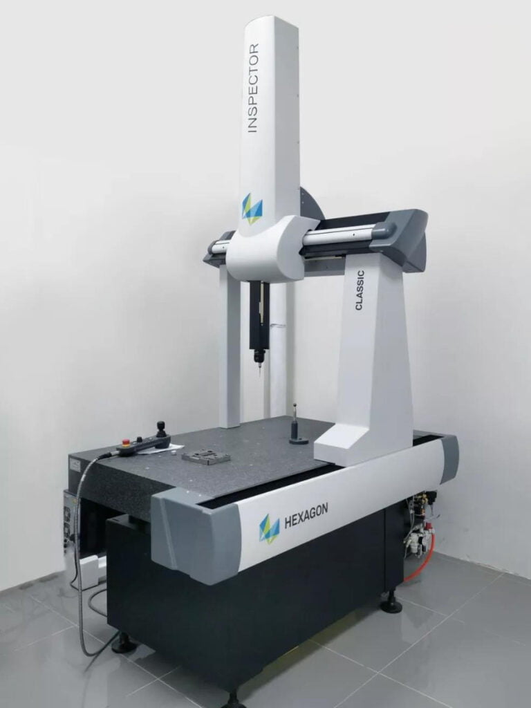
Measurements were made on optical and contact measuring equipment, and working profiles were defined to ±0.005 mm so that replacements would be interchangeable. For punches with complex profiles, the profile was scanned and verified against the die opening, not only against the worn punch.
Step three: rank die spare parts by criticality
Not every component deserves a spare on the shelf. We ranked each part into three classes with the plant’s maintenance and planning teams:
| Class | Definition | Stocking rule | Share of parts |
|---|---|---|---|
| A | Failure stops the press; part is custom and has failed before | At least one set in a die kit on site, reorder at one | about 18% |
| B | Failure slows production or needs a workaround | Stocked centrally, reorder from consumption | about 32% |
| C | Routine wear, long life, or standard catalogue part | Drawing on file, made or bought on demand | about 50% |
Classes were reviewed every quarter using the plant’s failure log.
Step four: make interchangeable die spare parts
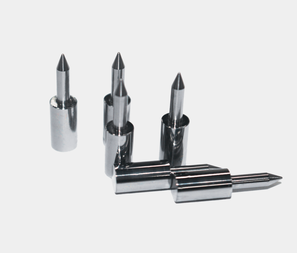
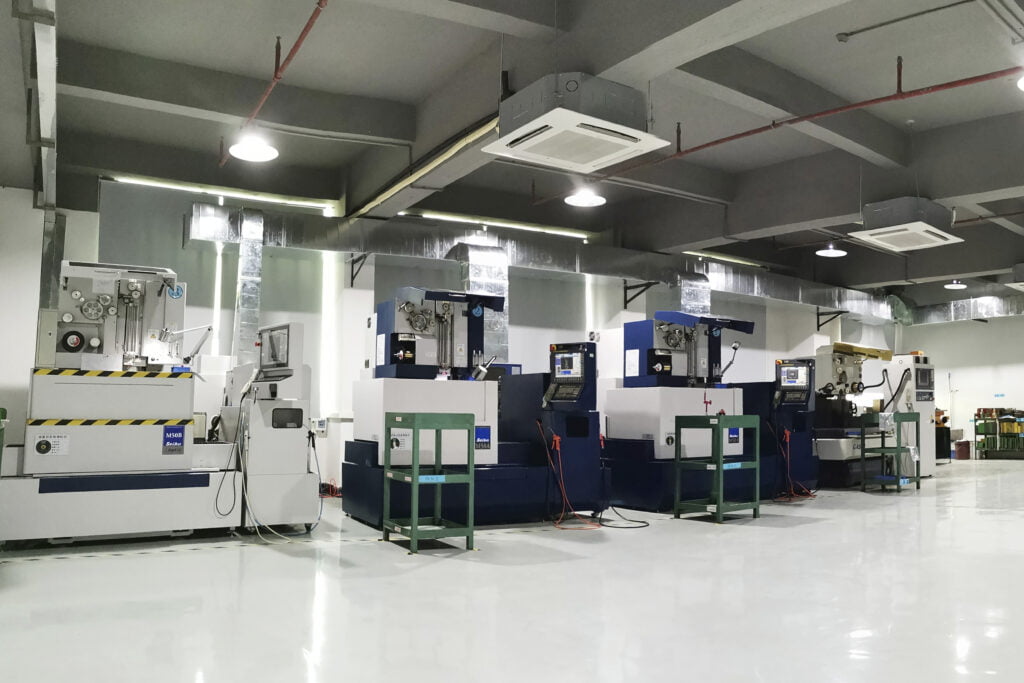
We manufactured the A-class kits first, die by die, in order of downtime impact. Punches and inserts were made from the original materials unless the failure history suggested an upgrade. For stations where D2 punches chipped repeatedly in thin stainless, we switched to coated PM high speed steel or carbide, following the logic in our carbide punch versus tool steel guide. Each part was profile ground or wire cut, hardened, measured and marked with its part number and die number.
Kits were packed per die, in labelled boxes with a contents list and the station map, so a maintenance technician could take the kit to the press and find the right part in seconds. The first kits for the ten most critical dies arrived in week ten.
Step five: min-max stock and replenishment
Die spare parts kits solve the first failure; replenishment solves the next one. For every A and B-class part we set a minimum and maximum stock level from its failure rate and our lead time, and the plant’s maintenance system raised a reorder when stock hit the minimum. Standard replenishment runs on a four-week cycle by sea freight; A-class parts can be made and air shipped within 72 hours when a failure is unexpected. Because the drawings are standardized, replenishment does not need quotes or clarifications, only a part number and a quantity.
Step six: track component life
The plant began logging each replacement against the part number and the press stroke counter. After a few months, the data showed which die spare parts were wearing faster than expected, which pointed to alignment, lubrication or clearance problems in specific stations. Several of those were fixed at root, so the part stopped failing rather than being replaced faster.
Training the maintenance team
Tools and parts only help if the people at the press use them the same way every time. Together with the plant’s maintenance lead we wrote a one-page swap procedure for each die: how to lift the die, which plates to remove to reach each station, torque values, how to check the new punch against the die opening, and how to record the swap. Technicians on both shifts practised swaps on dies in the toolroom before the kits reached the presses. The station maps in each kit use the same numbering as the procedure, so the technician at the press, the planner raising the reorder and our team making the part all refer to the same component in the same way.
The procedure also changed what happens after a swap. The broken part is bagged with a tag and returned to the toolroom, where the cause is recorded: wear, chipping, breakage from a misfeed, or damage from a neighbouring failure. That tag is what feeds the quarterly review, and it is why the plant could fix several stations at root instead of simply consuming spares faster.
Die spare parts program results
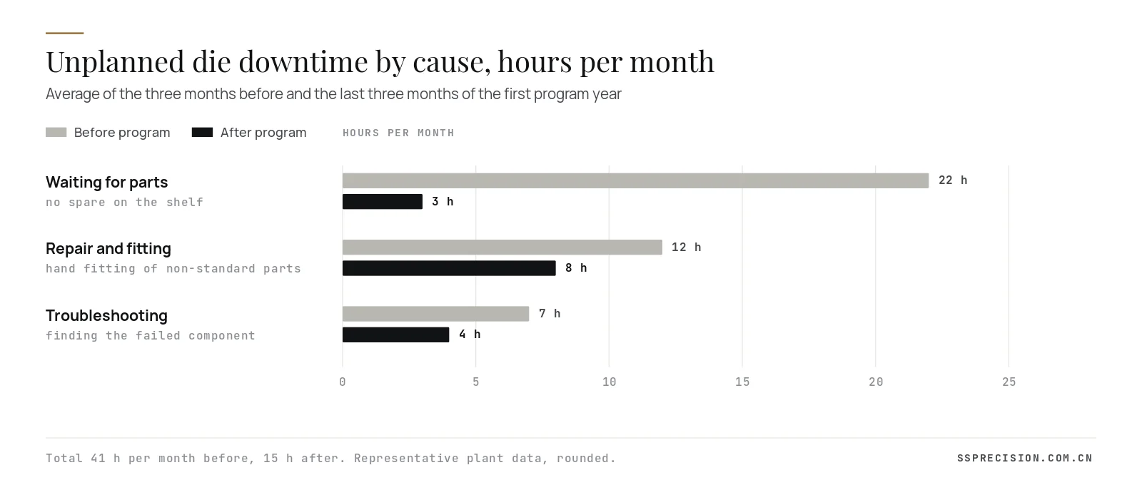
The biggest gain was the collapse of waiting time. With interchangeable spares on the shelf, a broken punch became a swap of about an hour instead of a stoppage of days. Repair and fitting time also fell, because parts no longer needed hand fitting, and troubleshooting fell because station maps and part numbers made it faster to find the failed component.
| Measure | Before | After 12 months |
|---|---|---|
| Unplanned die downtime per month | 41 hours | 15 hours |
| Mean time to repair a die breakdown | 5.2 hours | 1.4 hours |
| Emergency air freight orders per quarter | about 25 | about 5 |
| Dies with complete drawings for wear parts | 11 of 40 | 40 of 40 |
| Unique wear part numbers | about 1,150 | about 980 after commonization |
| Overall equipment effectiveness, press lines | about 64% | about 70% |
Figures rounded from the plant’s maintenance and production records.
What goes into a die spare parts kit
The contents of each kit were set from the failure history of that die, but most kits followed the same pattern. The table shows a typical kit for a 16-station progressive die making an electrical bracket in 1.0 mm galvanized steel.
| Component | Quantity in kit | Material | Why it is included |
|---|---|---|---|
| Piercing punches, small holes | 2 of each size | PM high speed steel, coated | Most frequent breakage in the die |
| Die buttons for those punches | 1 of each size | Carbide | Chipping after slug pulling |
| Pilots | 2 of each size | High speed steel | Bent or broken on misfeeds |
| Trim punch inserts | 1 set | D2, 60 HRC | Edge chipping at the carrier cut |
| Forming insert, critical bend | 1 | DC53, coated | Cracking after long runs |
| Stripper inserts and guide bushings | 1 set | Hardened tool steel | Worn guides cause punch breakage |
| Die springs and lifters | 1 set | Catalogue parts | Cheap, and often the hidden cause |
Including stripper inserts and springs may look unnecessary, but worn guides and tired springs were behind a large share of punch breakages. Replacing them together with the punch stopped the same failure returning a week later.
Material upgrades found along the way
The audit also showed where the original material choice no longer suited the job. Several dies had been built for mild steel and were now running stainless or pre-coated material for newer part numbers. Their D2 piercing punches chipped every few days. Moving those die spare parts to coated PM high speed steel, and in two thin-stainless stations to carbide, multiplied punch life several times. In a few forming stations we did the opposite and moved from a very hard grade to a tougher one, because cracking rather than wear was the failure. Each change was recorded on the drawing, so the upgrade carries forward into every future spare.
Die spare parts for dies built by other toolmakers
Only a few of the 40 dies had been built by us. That is common: most plants run tooling from several sources, and the original toolmaker may be far away, busy or no longer in business. Making die spare parts for someone else’s die is mainly a question of measurement and discipline. We measure the die openings and retainers, not only the worn part, so that the spare restores the original clearance; we confirm fits on the first part in the die before making quantities; and we keep the drawings under revision control so that any later change to the die is reflected in the spares. The plant owns the drawings, so it is never locked in to one supplier.
How to start a die spare parts program in your plant
- Log every die breakdown for three months: die, station, component, time the press was stopped and why.
- Rank components by the press hours their failures cost, not by their price.
- Collect or create drawings for the top 10 to 15% of components, with fits, profiles and materials defined.
- Stock one set of those die spare parts per die, packed and labelled by die and station.
- Set minimum and maximum stock levels and a fixed replenishment cycle with your supplier.
- Review the log each quarter, move parts between classes and fix stations that consume spares too fast.
The economics of die spare parts
Holding die spare parts costs money: the parts themselves and the cash tied up in inventory. The plant’s controller asked the obvious question at the start of the program, and the answer came from the downtime numbers. Twenty-six recovered press hours a month, at the plant’s contribution margin per press hour, paid for the first year’s A-class kits in a little over four months. Removing most air freight and overtime covered the replenishment stock. The inventory value on the shelf ended the year at roughly one tenth of the value of the dies it protects, which the plant now treats as insurance on its most productive assets.
There were softer gains too. Planners stopped padding delivery schedules with buffer stock of finished parts to cover die breakdowns, which released warehouse space and working capital. Customer delivery performance improved, and two customers that had audited the plant’s tooling risk in the previous year closed their findings after reviewing the die spare parts program and its records.
Die spare parts lessons for any stamping plant
- Start from failure data. A small share of components causes most of the downtime; stock those first.
- Drawings before parts. Interchangeable die spare parts need a drawing with the right tolerances; measuring the broken part is not enough.
- Standardize and commonize. One drawing standard and shared part numbers cut stock and ordering effort.
- Kit by die. A labelled kit at the press turns a search into a swap.
- Replenish automatically. Min-max levels and fixed part numbers remove quoting from the critical path.
- Use the data. Parts that fail too often point to die problems worth fixing at root.
If you do not know which components cause most of your die downtime, start logging each replacement with a part number and a stroke count. Three months of data is usually enough to decide what belongs on the shelf.
Die spare parts program timeline
- Weeks 1 to 2: on-site audit of 40 dies, maintenance record analysis, downtime baseline.
- Weeks 3 to 8: reverse engineering and drawings for the ten most critical dies, criticality ranking workshop.
- Weeks 6 to 10: manufacture of A-class kits for those ten dies, first delivery in week ten.
- Months 3 to 6: drawings and kits for the remaining 30 dies, min-max levels set, replenishment cycle started.
- Months 6 to 12: life tracking, root cause fixes on fast-wearing stations, quarterly class review.
Losing press hours waiting for die parts?Send a list of your dies or a few worn components with photos. We will propose an audit plan and quote the first critical kits.
Request a quoteDie spare parts from SSP
We manufacture punches, die buttons, inserts, pilots, guide components, lifters and stripper inserts to customer drawings or from reverse engineered samples, for dies built by us and by other toolmakers. The tooling spare parts page lists the component types we make, and our tooling spare parts manufacturing page explains materials, tolerances and delivery options. When a die is beyond economic repair, our stamping die manufacturing team can rebuild it with interchangeable inserts designed in from the start. For more on the maintenance side, read our guide to warning signs your stamping dies need maintenance, and for the general principle behind the program, the idea of total productive maintenance.
Die spare parts FAQ
Which die spare parts should a stamping plant keep in stock?
Keep spares for custom components whose failure stops the press and that have failed before: typically piercing punches, die buttons, pilots and heavily loaded inserts. Maintenance records usually show that a small share of parts causes most downtime.
Can die spare parts be made without original drawings?
Yes. Components can be reverse engineered from samples and from the mating features in the die, then drawn with proper tolerances so that future spares are interchangeable without hand fitting.
How accurate must replacement punches be?
Working profiles are typically held to ±0.002 to 0.005 mm, with controlled fits to the retainer and a defined regrind allowance, so the spare drops into the die without fitting and holds the original clearance.
How quickly can SSP deliver die spare parts?
Planned replenishment usually runs on a four-week cycle. For critical parts with approved drawings, we can manufacture and air ship within about 72 hours when an unexpected failure occurs.
Is it worth upgrading spare punches to carbide?
Where a punch wears out rather than breaks, in thin abrasive material at high volume, an upgrade to carbide or coated PM steel often cuts regrinds and downtime. Where punches break from impact or misfeeds, a tougher steel is usually better.
Customer name and some figures are anonymized or rounded to protect confidentiality.