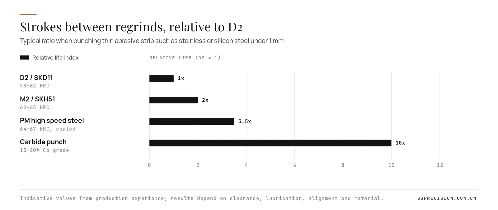
A carbide punch can run ten times longer between sharpenings than a D2 punch in the same die. It can also shatter on the first misfeed. Whether it is the right choice depends on the material you cut, the thickness, the volume and how well the die guides the punch.
We make both kinds every week, as original die components and as replacement spares for customers’ dies. This guide sets out how our engineers decide between a carbide punch and a tool steel punch: what the materials are, how hardness and toughness trade off, how clearance and edge preparation change, what wear life to expect, how regrinding works and what the choice really costs per million strokes.
- Choose a carbide punch for thin, abrasive material at high volume: stainless, electrical steel, and copper alloy terminals under about 1 mm.
- Choose tool steel or powder metallurgy high speed steel for thick or high strength material, heavy impact, long unsupported punches and low volume.
- Carbide is about three times stiffer than steel but far less tough, so guiding, alignment and misfeed detection decide whether it survives.
- Carbide grades with more cobalt are tougher; grades with less cobalt and finer grains wear better.
- Judge cost per million strokes, including regrinds and downtime, not the price of the punch.
What a carbide punch is made of
Cemented carbide is not a steel. It is a composite of tungsten carbide grains, usually 0.5 to 5 µm across, held in a cobalt binder that makes up about 6 to 25% of the weight. The carbide grains give extreme hardness and wear resistance; the cobalt gives the toughness that keeps the part from behaving like a ceramic. The material is pressed from powder, sintered at around 1,400 °C and then ground or EDM machined to shape.
Compared with hardened tool steel, a carbide punch has three properties that matter in a die:
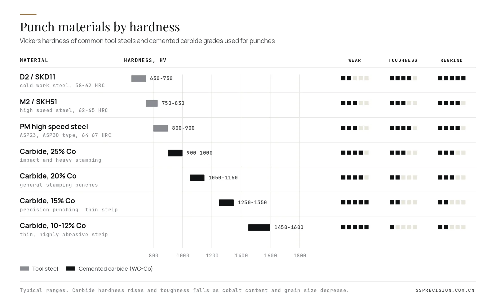
- Hardness: roughly 900 to 1,600 HV depending on grade, against 650 to 900 HV for hardened tool steels.
- Stiffness: a Young’s modulus of about 550 to 630 GPa, nearly three times that of steel, so a slender carbide punch deflects far less under load.
- Toughness: much lower. Transverse rupture strength is high, but fracture toughness is a fraction of steel’s, so carbide tolerates compression well and bending or impact poorly.
It is also nearly twice as dense as steel and several times more expensive per kilogram, and it can only be shaped by diamond grinding or EDM.
The tool steel alternatives
Tool steel punches cover a wide range, and the modern powder metallurgy grades have narrowed the gap to carbide considerably.
| Material | Typical hardness | Strengths | Limits |
|---|---|---|---|
| D2 / SKD11 / 1.2379 | 58 to 62 HRC | Low cost, good wear for mild steel, easy to machine and grind | Coarse carbides chip on thin, hard material |
| DC53 / modified 8% Cr | 60 to 63 HRC | Tougher than D2 at similar hardness, better for EDM | Moderate wear gain over D2 |
| M2 / SKH51 / 1.3343 | 62 to 65 HRC | Higher hardness and hot hardness, good for small punches | Needs careful heat treatment |
| PM high speed steel (ASP23, ASP30 type) | 64 to 67 HRC | Fine, even carbides; best toughness at high hardness; coats well | Higher cost than conventional steels |
| Cemented carbide (WC-Co) | 900 to 1,600 HV | Highest wear resistance and stiffness | Brittle; expensive; diamond grinding only |
Coatings shift the balance again. A PVD coating such as TiCN, TiAlN or CrN on a PM steel punch can double or triple its life in stainless and coated steel, often at a lower total cost than a carbide punch, and without the fracture risk.
Choosing a carbide punch grade
Carbide grades for stamping are designated differently by each producer, but they follow the same logic: cobalt content and grain size.
- 10 to 12% cobalt, fine grain: the hardest practical punch grades. Best edge retention in thin, abrasive strip such as electrical steel laminations and stainless below 0.5 mm, where impact is low and alignment is excellent.
- 15% cobalt: the usual choice for a precision carbide punch in terminal and lead frame dies, balancing wear and chipping resistance.
- 20% cobalt: general stamping punches and die inserts where some impact is present.
- 25% cobalt: impact grades for heavier material and forming punches, approaching the toughness of tool steel with better wear resistance.
Start one grade tougher than you think you need. A chipped carbide punch fails suddenly and can damage the die insert and stripper with it, while a slightly softer grade simply needs one more regrind per year.
When a carbide punch pays off
Carbide earns its price when wear, not fracture, is what ends a punch’s life. The typical cases are:
- Thin, abrasive or hard material: stainless steel, silicon electrical steel, spring steels and phosphor bronze below about 1 mm.
- High volume: dies running tens of millions of strokes a year, where each regrind means downtime.
- Small, precise holes and profiles: fine pitch terminals and lead frames where a few microns of wear change the part.
- High speed: presses above 400 strokes per minute, where heat and wear accelerate.
- Stiffness-critical punches: slender piercing punches where steel would deflect and wander.
When a tool steel punch is the better choice
Tool steel wins when the punch is at risk of breaking rather than wearing out:
- Material thicker than about 2 mm, or high strength steels above 780 MPa, where punching loads and impact are high.
- Long, unguided or lightly guided punches, and punches that see side loads from uneven cutting.
- Dies with a history of misfeeds or slug pulling, or without reliable misfeed sensors.
- Forming and embossing punches that see bending loads.
- Low volume parts, where the punch never wears out anyway.
For many of these, PM high speed steel with a PVD coating is the sweet spot: close to carbide wear life in medium volumes, with the toughness of steel.
Clearance and edge preparation for a carbide punch
Clearance is the gap between punch and die, measured per side as a percentage of material thickness. It sets the shape of the cut edge and the load on the punch edge.
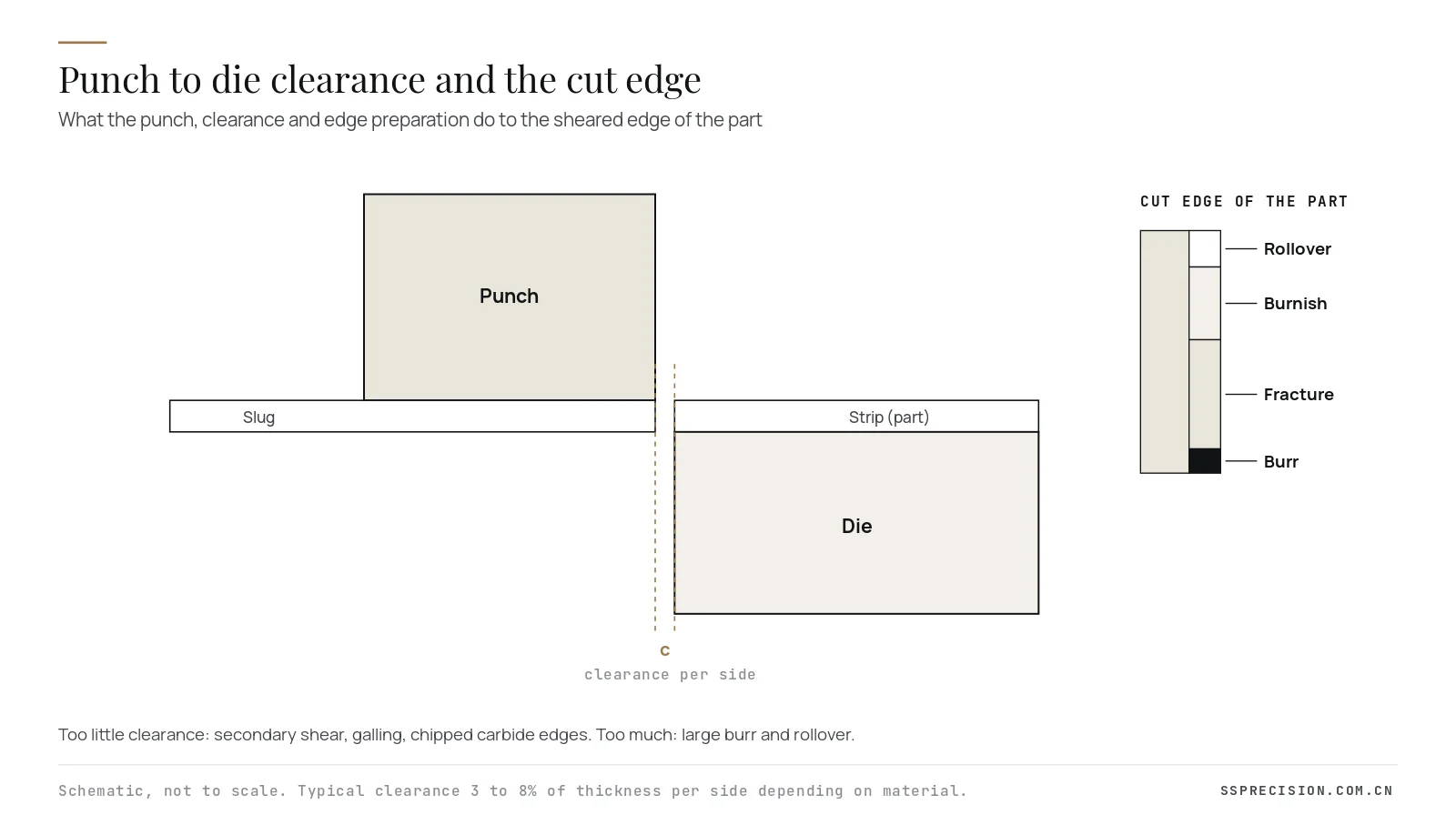
For a carbide punch we generally hold clearance at the same or slightly larger values than for steel, because a very tight clearance raises edge stress and invites chipping. Typical starting points are 3 to 5% per side for copper alloys, 5 to 7% for mild steel and 6 to 8% for stainless, adjusted after tryout. The cutting edge is lightly honed, typically to 0.005 to 0.02 mm, so it does not start micro-chipping on the first stroke.
Other design rules that keep carbide alive:
- Guide the punch through a hardened stripper insert with a close fit, so the stripper carries side load, not the punch.
- Keep the length to diameter ratio low and add a generous radius at every shoulder; carbide hates stress concentrations.
- Grind a slight back taper behind the land to reduce stripping friction and slug pulling.
- Mount the carbide in a steel retainer or shrink-fit sleeve rather than clamping it at a sharp corner.
- Fit misfeed and slug detection sensors; carbide does not survive a double hit.
Carbide can be wire cut, but conventional EDM can leach cobalt from the surface and leave micro-cracks. We cut carbide on anti-electrolysis generators with multiple skim passes, then grind or polish the working land so no recast layer remains at the cutting edge.
Regrinding and maintenance
A worn punch shows it through burr height. We set a burr limit on the part drawing, usually 5 to 10% of material thickness, and schedule regrinds by stroke count before that limit is reached. A carbide punch is typically reground by 0.03 to 0.05 mm per sharpening, because it wears slowly and evenly. A steel punch often needs 0.1 to 0.2 mm, since wear is rounder and deeper. Both need enough length allowance and a way to restore shut height, usually shims under the punch head or a ground spacer.
Track life per punch, not per die. When one station wears faster than the others, it is usually misaligned, under-lubricated or seeing the wrong clearance. Our guide to tracking tool wear in progressive dies explains how to set up that record.
Carbide punch cost per million strokes
The price of a carbide punch is often three to six times that of the same punch in D2. That comparison misleads, because the punch is only a small part of what wear costs. Consider a punch that pierces 0.3 mm stainless at 600 strokes per minute:
| Item | D2 punch | Carbide punch |
|---|---|---|
| Strokes between regrinds | about 300,000 | about 3,000,000 |
| Regrinds per 10 million strokes | about 33 | about 3 |
| Die pulls for sharpening | about 33 | about 3 |
| Press downtime at 2 hours per pull | about 66 hours | about 6 hours |
| Punches consumed per 10 million strokes | 3 to 4 | usually 1 |
Illustrative example. Actual values depend on the part, die condition and press.
Even if the carbide punch costs five times more, sixty hours of recovered press time on a high speed line is worth far more than the difference. The calculation reverses on a low volume die running mild steel, where a D2 punch may never need a regrind in its whole life.
Coatings and surface treatments
A PVD coating adds a hard, low friction layer of 2 to 5 µm on the working surfaces. On steel punches it is the cheapest way to extend life, especially against galling in stainless steel, aluminum and zinc coated sheet. The common choices are TiCN for general wear, TiAlN or AlCrN where heat builds up at high stroke rates, CrN for copper and aluminum where adhesion is the problem, and DLC for non-ferrous metals and dry or lightly lubricated punching.
Coatings on carbide are less common in punching, because carbide already resists wear, but they help when galling rather than abrasion limits life. The substrate must be hard enough to support the coating: on steels below about 60 HRC, a thin hard coating can crack like ice on soft ground. That is another reason PM high speed steel at 64 to 67 HRC pairs well with coatings.
Whatever the coating, the surface under it matters. Punch lands should be ground or polished to a low roughness in the direction of travel before coating, and regrinding removes the coating from the end face, so the benefit falls after each sharpening unless the punch is recoated.
Do not forget the die side
A punch cuts against a die button or die insert, and the two wear together. Pairing a carbide punch with a steel die button moves the wear to the die, and a worn die opening raises burr just as a worn punch does. In high volume terminal and lamination dies we therefore make die inserts in carbide too, often in a slightly tougher grade than the punch, and we design them as replaceable inserts pressed or clamped into a steel die block so they can be changed without re-machining the block.
Stripper inserts deserve the same thought. The stripper guides the punch, and on a carbide punch any play in that guide becomes side load on a brittle part. Hardened stripper inserts with a close sliding fit, checked at every die maintenance, are cheap insurance.
An example from our toolroom
A customer running a progressive die for 0.25 mm stainless shield frames was regrinding its D2 piercing punches every 250,000 to 300,000 strokes, which meant pulling the die almost every shift. We reviewed the die and found the stripper guides were worn, which explained some chipping on the D2 edges. After replacing the stripper inserts and fitting 15% cobalt carbide punches with honed edges and matching carbide die buttons, the interval between regrinds rose to roughly 2.5 to 3 million strokes. The punches cost more, but the die now comes out for sharpening about once every two weeks instead of every day.
How to specify a carbide punch on a drawing or order
Many replacement punch orders arrive with a sketch and the word “carbide”. That leaves too much to guesswork. A complete specification lets any competent toolroom make an interchangeable part:
- Material and grade, for example a 15% cobalt carbide or its producer designation, and the minimum hardness.
- Working profile with tolerance, usually ±0.002 to 0.005 mm, and its datum relative to the head or shank.
- Land length, back taper or relief behind the land, and edge hone.
- Shank diameter and fit class to the retainer, head geometry and overall length, including regrind allowance.
- Surface finish of the land and any coating.
- Whether the matching die button should be supplied as a set.
With that information we can produce a carbide punch that drops into the existing retainer without fitting, which is the whole point of a spare.
Six factors that decide the best choice
- Material: thin and abrasive favours carbide; thick and high strength favours steel.
- Volume: millions of strokes per year favour carbide; low volume favours steel.
- Punch geometry: short and well guided suits carbide; long, slender or side-loaded suits steel.
- Die condition: new, well aligned dies with sensors suit carbide; older dies with play or misfeeds suit steel.
- Precision: fine pitch features that must hold size over millions of parts suit carbide.
- Total cost: compare cost per million strokes including downtime, not purchase price.
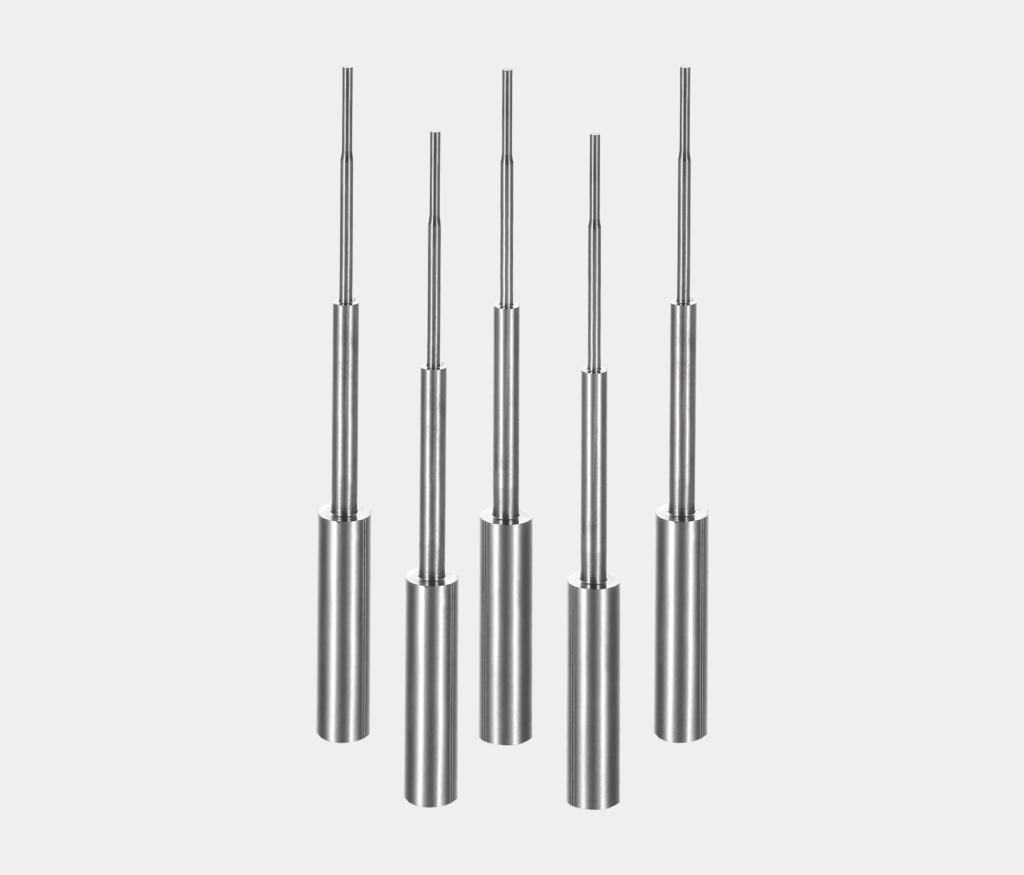
Need replacement punches or an upgrade to carbide?Send the punch drawing or a sample with your material and stroke rate. We will recommend steel or carbide and quote made-to-print spares.
Request a quoteCarbide punch and die spares from SSP
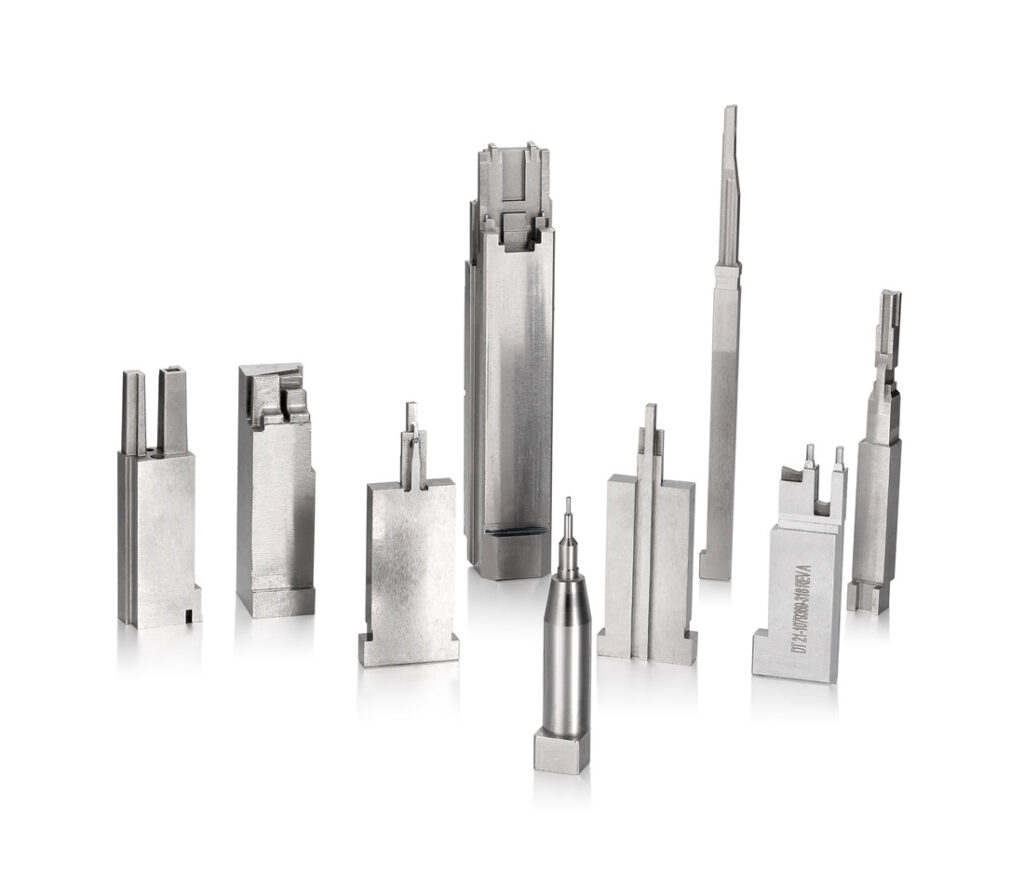
Our toolroom in Dongguan grinds and wire cuts punches, die buttons, inserts and pilots in D2, DC53, M2, PM high speed steel and carbide, for our own dies and as tooling spare parts for customers worldwide. Profiles are held to ±0.002 mm where the design needs it and verified on optical and contact measuring equipment. Through our made-to-print spare parts manufacturing program, customers keep interchangeable spares on the shelf so a worn or broken punch is a swap, not a stoppage.
For die design context, see our pages on stamping die manufacturing and our comparison of D2 and DC53 tool steel. Background on the material itself is in this overview of cemented carbide.
Carbide punch FAQ
How much longer does a carbide punch last than a steel punch?
In thin, abrasive material a carbide punch typically runs five to ten times longer between regrinds than D2. In thick or high strength material the gain is smaller and the risk of chipping is higher, so PM steel is often the better choice.
What cobalt content should a carbide punch have?
About 15% cobalt suits most precision punching of thin strip. Use 10 to 12% for maximum wear resistance in very thin abrasive material, and 20 to 25% where the punch sees impact or heavier loads.
Why do carbide punches break?
Most breakages come from misfeeds, slug pulling, side loads from poor guiding, misalignment, clearance that is too tight, or sharp internal corners. Carbide is strong in compression but weak in bending and impact.
Can a carbide punch be reground?
Yes. Carbide punches are reground with diamond wheels, typically removing only 0.03 to 0.05 mm per sharpening. Keep enough length allowance and restore shut height with shims or spacers.
Is PM high speed steel a good alternative to a carbide punch?
Often yes. Coated PM high speed steel at 64 to 67 HRC combines good wear resistance with much higher toughness, and it is a safer choice for medium volumes, thicker material or dies with a misfeed history.