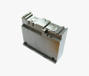
EV battery cell spacer design should begin with a verified cell envelope, a defined locating strategy, and a separate electrical-insulation assessment. A molded holder that fits nominal cells is not yet a validated battery component. This guide proposes a practical review sequence for dimensions, material evidence, assembly fit and acceptance records. Published BASF and Covestro examples demonstrate that engineered plastics are used for cell holders, but those examples do not qualify a different resin or component. [1] BASF; [2] Covestro.
Engineering answer in brief
- Separate location, retention, assembly clearance and insulation into individually verifiable requirements.
- Use the exact cell drawing and material grade, not a nominal cell-format name or generic polymer label.
- Calculate fit at dimensional extremes, then define which service states still require evidence.
- Review material tracking and flammability data within their actual test scope.
- Release the part only against traceable molded-part and assembly evidence.
This is a proposed engineering workflow. Its evidence boundaries follow the public scopes of [3] IEC 60112:2025, [4] IEC 60664-1:2020+AMD1:2025 CSV and [7] ISO 20457:2026, rather than substituting a single material rating for component approval.
Define the functions before choosing a cell-holder geometry
For this study, “spacer” means a molded component intended to position cells relative to a module datum. Treat retention and electrical separation as additional functions only when the product specification assigns them to that component. This definition prevents a pocket diameter from silently becoming the acceptance criterion for every battery requirement.
The recommended first document is an interface map. Mark the cell envelope, sleeve or coating where present, permitted contact regions, nearby conductors, joining access and the module locating features. Ask the cell supplier to approve the contact restrictions and provide the relevant dimensional states. Do not assume the metal can, external insulation or terminal geometry is represented by the same nominal diameter.
Record which part establishes position. A pocket may locate a cell while another feature provides retention; alternatively, the assembly may use an approved adhesive system. Make the intended architecture explicit before analyzing dimensions. If retention is outside the spacer’s scope, write that exclusion into the drawing-review record instead of leaving the responsibility uncertain.
| Required input | Question for the project owner | Recommended record |
|---|---|---|
| Cell envelope | Which revision and dimensional states govern fit? | Approved supplier drawing and contact restrictions |
| Location | Which features establish cell and module position? | Datum and assembly interface map |
| Retention | Which component or joint resists the specified loads? | Load cases and joining specification |
| Insulation | Which conductive pairs and insulation functions need assessment? | Electrical safety requirements owned by the responsible engineer |
| Environment | Which temperature, humidity and chemical exposures apply? | Service profile and material compatibility plan |
| Acceptance | Who approves dimensions, fit and system safety? | Named responsibilities and evidence requirements |
This is an original review worksheet, not a battery standard or a record of SSP testing.
Build a material shortlist from evidence, not polymer names
BASF documents a specific RML immersion-cooled battery using Ultramid A3EG6 EQ for individual cell holders. Its account discusses the grade’s purity and interaction with dielectric fluid. Covestro separately describes PC+ABS blends for cylindrical-cell holders and highlights mechanical and molding requirements. These are supplier application examples with different conditions, not evidence that PA66 and PC+ABS are interchangeable. [1] BASF; [2] Covestro.
Use these examples to formulate supplier questions. Ask for the exact commercial grade, reinforcement, flame-retardant formulation, color designation and processing information. Request evidence relevant to the proposed thickness and environment. Keep a change log: a supplier’s approval for one formulation should not be treated as permission to substitute a visually similar resin.
The recommended comparison does not assign a universal winner. Instead, give each candidate the same evidence fields and identify missing data. A supplier brochure can establish why a grade deserves investigation; it cannot close a requirement that needs component testing. Do not populate a blank field with a value copied from another grade in the same polymer family.
| Evidence field | What to request | What it does not establish |
|---|---|---|
| Exact formulation | Grade, color, reinforcement and traceability documents | Approval of a later formulation change |
| Molding behavior | Supplier processing and dimensional data for the selected grade | The final shape of every molded pocket |
| Tracking resistance | Relevant report, method and specimen condition | A complete electrical-insulation design |
| Flammability | Applicable classification and supporting material record | Whole-module fire performance |
| Environmental exposure | Evidence for the actual fluid, humidity and temperature profile | Compatibility with unspecified chemicals |
This table is a procurement recommendation. Its separation of tracking, flammability and dimensional evidence reflects the distinct subjects covered by IEC, UL and ISO. [3] IEC 60112:2025; [5] UL Solutions; [7] ISO 20457:2026.
Do not confuse battery cell holder insulation with a material rating
Tracking results are not a voltage rating for the spacer
IEC 60112:2025 characterizes proof and comparative tracking indices of solid insulating materials using an alternating-voltage test. Its public scope states that composition and surface condition influence results, and that the results are not directly suitable for determining safe creepage distances. A CTI value is therefore not a permitted battery operating voltage or a stand-alone spacing instruction. [3] IEC 60112:2025.
The design recommendation is to identify the relevant conductive pairs and ask the responsible electrical engineer to specify the insulation function and assessment basis. Retain the material evidence with its test conditions. Do not turn the hypothetical cell-pocket gap below into an electrical clearance, creepage path or dielectric-withstand requirement.
Insulation coordination and fire behavior need separate evidence
The public scope of IEC 60664-1:2020+AMD1:2025 covers insulation coordination and addresses clearances, creepage distances and solid insulation within its stated equipment scope. It also excludes certain paths, including through liquid insulation. Use the applicable product requirements and competent assessment for the actual battery architecture rather than transferring air-spacing guidance to an immersion-cooled design. [4] IEC 60664-1:2020+AMD1:2025 CSV.
UL explains that UL 94 evaluates plastic flammability in small-scale controlled tests. That subject is different from the battery assembly’s behavior. The engineering recommendation here is to maintain separate acceptance lines for material flammability, electrical insulation and system-level validation. Neither a favorable material rating nor a successful fit check closes the other lines. [5] UL Solutions.
This article intentionally provides no high-voltage test settings or universal minimum insulation distance. Those must come from the applicable project requirements and qualified assessment, not from a general molding guide.
EV battery cell spacer design: a reproducible fit example
Consider a hypothetical circular envelope of 21.00 ±0.05 mm and a hypothetical molded pocket of 21.40 ±0.10 mm. These dimensions are invented for arithmetic only. They are not specifications for a commercial cell or a recommended pocket. Assume concentric ideal circles at one reference condition and ignore form, position, surface condition and deformation for this first calculation.
The envelope ranges from 20.95 to 21.05 mm; the pocket ranges from 21.30 to 21.50 mm. Diametral clearance is pocket diameter minus envelope diameter. Its minimum is 21.30 − 21.05 = 0.25 mm. Its maximum is 21.50 − 20.95 = 0.55 mm. Under the concentric-circle assumption, the corresponding radial clearances are 0.125 and 0.275 mm.
| Hypothetical check | Calculation | Result | Interpretation boundary |
|---|---|---|---|
| Minimum diametral clearance | 21.30 − 21.05 | 0.25 mm | Ideal circles at the reference condition only |
| Maximum diametral clearance | 21.50 − 20.95 | 0.55 mm | Does not establish retention |
| Concentric radial clearance range | 0.25 ÷ 2 to 0.55 ÷ 2 | 0.125–0.275 mm | Not an electrical spacing requirement |
| Assumed additional pocket closure | 0.25 − 0.12 | 0.13 mm diametral | The 0.12 mm change is hypothetical, not material data |
Now impose an additional, purely hypothetical 0.12 mm reduction of the minimum pocket diameter while leaving the maximum cell envelope unchanged. The remaining diametral clearance becomes 0.13 mm, or 0.065 mm radially for concentric circles. This sensitivity check illustrates how an unverified state change consumes a dimensional budget. It does not predict thermal expansion, moisture response or service performance.
For a second teaching example, assume eight pocket centers in a row with seven independently toleranced pitch intervals, each 23.00 ±0.08 mm. The nominal first-to-last span is 7 × 23.00 = 161.00 mm. Worst-case arithmetic accumulation is ±(7 × 0.08) = ±0.56 mm. This is a chain-dimension model, not a claim about the variation of a real molded tool. A datum-based position scheme requires its own interpretation.
Use these results to ask better drawing questions: must the row align with another component, how are centers controlled relative to the module datums, and what happens if a part passes individual diameters but misses the assembly interface? The recommendation is to review local fit and overall position separately, then define the actual measurement method.
Review the molded drawing and physical tool together
ISO 20457:2026 provides a plastics-specific framework for molded-part dimensional and geometrical tolerances and acceptance. ISO’s public overview identifies material behavior, shrinkage, processing, geometry and cooling-related effects as reasons a metal-part tolerance approach cannot simply be transferred to plastics. It does not supply a universal cell-pocket tolerance. [7] ISO 20457:2026.
The proposed tool review should identify pocket-forming features, datum-forming surfaces, the parting line and permitted gate/ejection contact zones. Mark any feature where a witness, offset or local variation would interfere with assembly. Ask the mold designer to explain how the critical features will be produced and inspected, including how cavity identity will remain traceable.
For the physical tooling discussion, see SSP’s injection mold tooling range. Confirm the actual resin, cavity layout and project acceptance requirements before ordering; this study does not establish that a particular battery tool configuration or tolerance is available.
Keep detailed gate selection in the separate gate-location and approval guide. Here, record only how the proposed gate and ejection arrangement affect the spacer’s restricted surfaces and validation plan. This keeps the application study focused on cell positioning rather than duplicating a general mold-design guide.

Plan dimensional stability and assembly validation before sampling
ASTM D618-21 explains that temperature and humidity affect physical and electrical test results, and that conditioning improves reproducibility without necessarily establishing equilibrium. It also gives precedence to the relevant material specification when its procedure differs. Accordingly, a report marked only “room temperature” is not a complete description of specimen history. [6] ASTM D618-21.
The following matrix is a recommended planning aid. It prescribes no universal exposure duration, sample count or battery qualification sequence. Ask the project owners to fill those fields before parts are tested. For hazardous electrical, thermal or cell-based work, use the responsible organization’s qualified facilities and approved procedures.
| Review state | Proposed observations | Evidence to retain | Acceptance owner |
|---|---|---|---|
| Reference-condition molded parts | Pocket size, datum position, form and assembly interfaces | Part/cavity IDs, condition, method and raw measurements | Design and quality |
| Specified environmental states | Repeat the relevant dimensional and fit checks | Exposure history, measurement timing and differences | Material and product engineering |
| Assembly trial | Approved contact, alignment and retention requirements | Mating-part revisions, fixture definition and observations | Assembly engineering |
| Electrical assessment | Tests defined by the applicable safety plan | Qualified report linked to the actual material/part revision | Electrical safety lead |
| Release review | Close requirements individually, including unresolved failures | Signed evidence matrix and change-control triggers | Project approval authority |
Make a failure interpretable
As a proposed diagnostic method, distinguish a size failure from a location failure, a contact restriction from retention, and a material-document gap from an observed component failure. Retain measurements rather than recording only pass/fail. If the measurement method or fixture changes, record that change so an apparent improvement is not confused with a different inspection condition.
When a candidate fails, document the requirement, evidence and proposed action before changing resin or geometry. Retest the affected requirements after the change. Do not average away an unacceptable interface by combining it with unrelated passing dimensions. The objective is a traceable engineering decision, not a favorable summary percentage.
After the tool and acceptance plan are agreed, SSP’s plastic injection molding services are the separate production enquiry route. Supply the evidence requirements with the drawing so the discussion covers sampling and inspection as well as part geometry.
Drawing and release checklist
- Identify the exact cell and module drawing revisions and permitted contact zones.
- Assign location, retention and insulation responsibilities separately.
- Specify the resin grade, color and controlled formulation.
- Review tolerance extremes, overall datum relationships and relevant service states.
- Define gate, parting-line and ejection restrictions on functional surfaces.
- Record measurement conditions, methods, cavity identity and raw results.
- Keep material ratings separate from component and battery-system approval.
- Assign unresolved questions to named engineering owners.
- Define which material, tooling or process changes require re-review.
This checklist is an engineering recommendation. For orientation to the company’s tooling families, visit SSP Precision’s manufacturing overview. A useful next-step package is a marked interface drawing, exact resin specification and acceptance matrix, not a request for a supposedly universal battery-spacer dimension.
Frequently asked questions
What is the best plastic for an EV battery cell spacer?
There is no approved universal choice in this study. BASF and Covestro document different grades in different cell-holder applications. Use those as starting context, then obtain evidence for the exact material, geometry and environment of the proposed component. [1] BASF; [2] Covestro.
Does a high CTI establish the battery’s allowable voltage?
No. IEC 60112 characterizes tracking behavior under a specified test, and cautions against using the result directly to determine safe creepage distances. The component needs its own applicable insulation assessment. [3] IEC 60112:2025.
Does UL 94 V-0 prove a module will contain a battery fire?
Do not make that inference. UL 94 is a small-scale plastic flammability assessment. Keep whole-assembly behavior and material classification as separate evidence questions. [5] UL Solutions.
Can the example pocket dimensions be copied into a production drawing?
No. Every numerical input is hypothetical. The example demonstrates tolerance arithmetic only; it omits real cell geometry, positional variation, deformation and the applicable electrical requirements.
How should battery spacer dimensional stability be recorded?
The recommended report identifies part and cavity, material revision, conditioning/exposure history, measurement method, timing and raw dimensions relative to the agreed datums. Conditioning matters because temperature and humidity influence test results. [6] ASTM D618-21.
Technical references and evidence limits
Standards references below use publicly accessible scopes and overviews, not reproduced procedures or tolerance tables. Obtain the applicable authorized documents for project work. Supplier examples describe their named applications, not SSP projects.
- BASF: RML battery housing and cell-holder materials.
- Covestro: Powerful and safe battery home storage.
- IEC 60112:2025, corrected version 2026-02, public scope.
- IEC 60664-1:2020+AMD1:2025 CSV, public scope.
- UL: Understanding UL 94 Rating Certifications and Limitations.
- ASTM D618-21, public scope and significance.
- ISO 20457:2026, public overview.