






Check stamped bracket flatness on the mounting pad under the drawing’s inspection condition, then check local seating gaps in the assembly fixture. If the two checks disagree, report each against its own limit and use measurements after each forming stage to decide where to investigate.
Stamped bracket flatness starts at the mounting pad
First, mark the exact surface the drawing controls. The stamped bracket flatness example uses a bent steel part with one mounting pad beside a formed flange. The highlighted pad ends at the transition to the bend. The mating body has a prescribed seating fixture with a named gap check at the edge of the pad.
For stamped bracket flatness, start with the smallest separation of two parallel planes that enclose the controlled surface. That separation describes surface form. The fixture gap is a clearance measured at one specified stop under a defined restraint. KEYENCE’s metrology guide illustrates the enclosing planes and explains how sparse sampling or probe pressure can affect the observed result.
Next, write the two acceptance conditions separately. This study assumes a maximum of 0.30 mm for the unclamped pad and 0.15 mm for the local seating gap. These are example drawing limits. Follow the actual drawing and the edition it calls up for stamped bracket flatness. See ASME’s GD&T standard scope.
If an assembly has several separate bearing pads, have the design authority decide whether the intent is local form on each pad or their collective relation to a common mating plane. Draw the regions and specify what must be controlled before the supplier programs the gauge. This example addresses one pad and its local fit in one fixture.
Set up flatness inspection and the seating check
To explain how to measure bracket flatness, begin with the support sketch. Record which side faces up, where the part rests and the surface region included in the evaluation. In this study, the sample rests on identified supports without a clamp pushing the pad flat. For each flatness inspection, use the same orientation and support.
Then scan or measure the marked pad using the agreed grid or scan pattern. Include the center and the area beside the formed flange without sampling the transition radius. For stamped bracket flatness, use the agreed two-plane evaluation and document the sampled region, algorithm and units.
When planning flatness inspection on a thin part, check whether the probe or supports alter what you are trying to measure. Then use repeated placement to see how much the reported result changes. If a point is invalid because it lies on a burr or outside the defined pad, record the reason for its exclusion and follow the approved program.
Separately, specify where to locate the bracket, how to seat it, the permitted restraint, and where to measure the gap. In the fixture, locate the bracket in its intended assembly position. Keep that result separate from free state flatness because the surfaces are observed under different conditions.
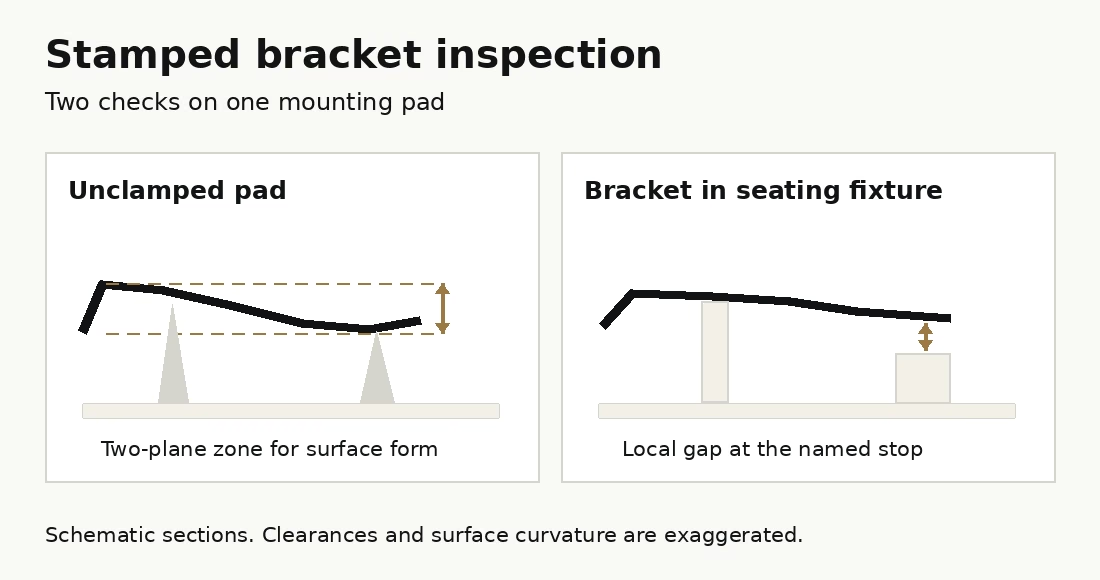
Before trusting a surprising result, take the part out of the fixture, repeat the specified seating sequence and record a second gap reading. Keep the stop and the measurement point fixed. If a burr, pin collision or unintended contact prevents the part from reaching the intended seat, resolve that setup problem before recording a result.
For suppliers asking how to measure bracket flatness on a bench, a straightedge can help locate a suspected high spot along a chosen line. Use the drawing-approved area method for the actual release result. For example, a single straightedge line leaves the rest of the area unsampled and gives incomplete evidence for stamped bracket flatness.
Find the station where the pad changes
Match the forming sequence to the measured shape
First, give the pad a feature ID and carry the same measurement region through each stage of the forming sequence. Keep the stock lot, delivery condition and thickness measurement with the sample record. For comparisons across several hits, record the sample identifiers so results from different pieces remain distinguishable.
After unloading at each available stage, measure stamped bracket flatness on the same support layout. If the fixed tool does not permit stopping at a stage or the part remains carried in a strip, use a qualified sampling route and document any change in constraint. Treat data gathered while attached to a carrier separately from the released-part data.
In the example, stamped bracket flatness changes most at the flange-forming operation. WorldAutoSteel’s springback guide describes angular change, wall curl and twist after unloading, as well as cases where shape changes after holes or reliefs are cut. A pad measurement tells the team where to investigate. A mapped shape and a controlled trial help distinguish possible causes.
| Condition at measurement | Pad flatness | Change from previous stage | Investigation |
|---|---|---|---|
| Blank released and supported | 0.14 mm | Baseline | Save the starting map and stock orientation. |
| Flange formed and unloaded | 0.35 mm | +0.21 mm | Compare the new deviations with the flange transition and inspect the support and forming conditions. |
| After final trim and release | 0.38 mm | +0.03 mm | Repeat the sample and retain the trim-stage map before attributing this small increment. |
Then compare the height maps and the two increments. The flange-forming change is 0.35 − 0.14 = 0.21 mm. The later change is 0.38 − 0.35 = 0.03 mm. Since both values are hypothetical, this example identifies a diagnostic priority only. With real data, review repeated results and the measurement system’s uncertainty before interpreting a small difference.
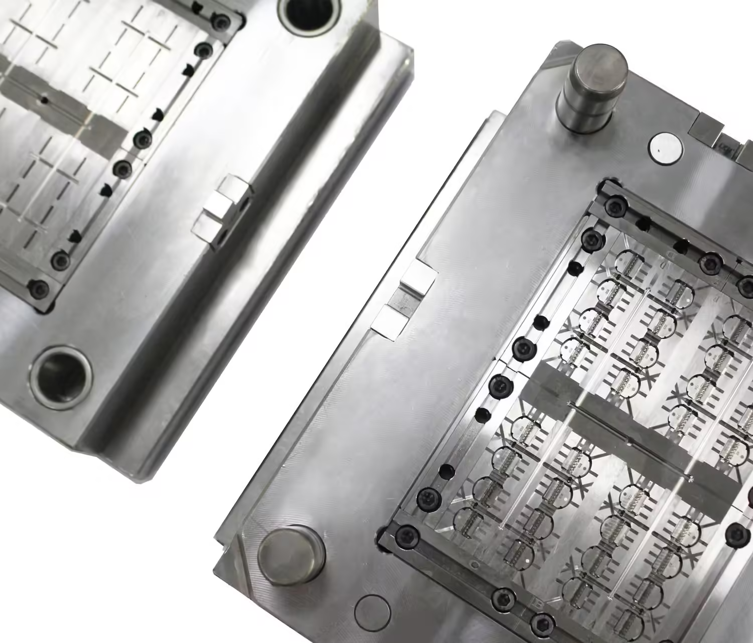
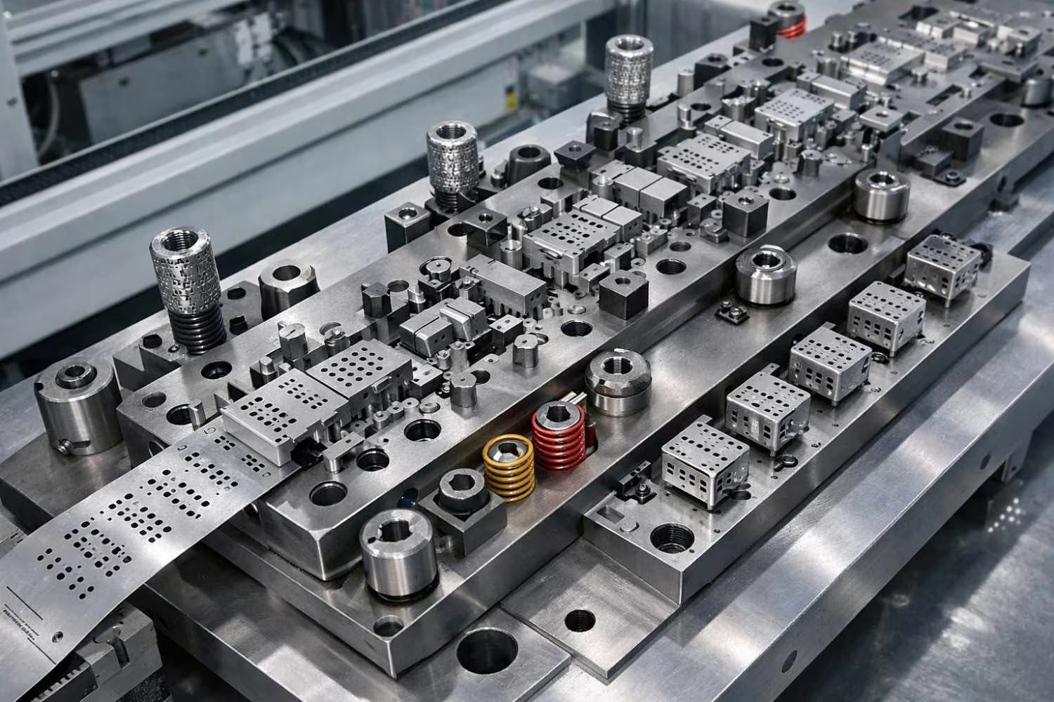
When stamped bracket flatness first exceeds the limit, mark the operation and build revision. For stamped bracket flatness, show the pad supports, the flange contact and the removal direction in the tooling review. Use the layout of the physical stamping die to identify which components can change local support between stations.
If changing the forming sequence is a proposed correction, keep a baseline and vary one agreed factor at a time. Remeasure the same pad and check the related angle, cut edge and interferences. Use the springback guide when reviewing angle recovery or twist as a separate response.
Record the two release decisions
At final inspection in this study, stamped bracket flatness is 0.38 mm against the 0.30 mm limit. The seating gap at the designated stop is 0.08 mm against 0.15 mm. Subtract the limit from the reading in both cases. A positive result exceeds the limit, and a negative result is below it.
| Requirement and condition | Limit | Result | Result minus limit | Decision |
|---|---|---|---|---|
| Pad flatness on defined supports, unclamped | ≤ 0.30 mm | 0.38 mm | +0.08 mm | Exceeds example limit. Hold for review. |
| Gap at the named fixture stop, under specified restraint | ≤ 0.15 mm | 0.08 mm | −0.07 mm | Meets the local gap requirement in this setup. |
Therefore, the illustrative bracket still fails the pad requirement even though it seats within the gap limit. If the drawing specifies both stamped bracket flatness and fixture seating, retain both results. Ask the responsible design authority for a documented disposition or a revised drawing if assembly function warrants a different acceptance condition.
When a result is near the limit, apply the project’s measurement decision rule. For example, if the allowed decision band for repeated placement spans the limit, have the quality team resolve the result before release. The numeric exercise above uses simple comparisons to demonstrate the logic. It does not specify a universal guard band.
For stamped bracket flatness at production approval, attach the drawing revision, fixture ID, support sketch and station log to the die development and tryout record. Include the correction tried, how the part was checked and what would trigger a fresh review at the next tool or material change.
Finally, if you bring the bracket to SSP Precision for a tooling discussion, share the identified pad, the assembly seating condition and the specific operation where the shape first changed. Those inputs give the tooling and quality teams the same acceptance question.
Key takeaways
- Define stamped bracket flatness and the fixture gap as independent checks, each with its own support or restraint.
- Track the pad through each available station with the same inspection region and evaluation method.
- Release against the actual drawing and keep both outcomes visible when the checks disagree.
Frequently asked questions
Can a seating gap prove free state flatness?
A local gap reports clearance at one point under the stated seating condition. A flatness result uses the sampled surface and its specified support condition. Record both when the drawing calls for both checks.
Where should I check the pad after a forming change?
Repeat stamped bracket flatness on the same drawing region. For example, include the edge near the modified feature and the pad center. Then verify any related dimensions that could have moved with the change.
Should a shop clamp the bracket to inspect the pad?
For stamped bracket flatness, follow the restraint specified in the drawing or approved inspection plan. If the specified condition is unclamped, use the documented supports without adding hold-down force at the pad. Keep any restrained fixture readings in a separate record.