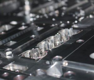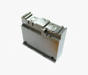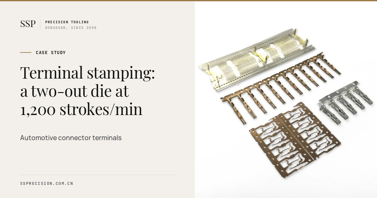
This terminal stamping case study follows one of our progressive die projects for an automotive connector maker. The customer’s existing die could not keep up with a new vehicle program, and its process capability on the contact spring was too low to pass a customer PPAP. Eleven weeks after purchase order, a new two-out die was running at 1,200 strokes per minute with every special characteristic above Cpk 1.67.
- Customer
- Connector maker supplying European automotive Tier 1s
- Part
- Female receptacle terminal for 0.64 mm tabs
- Material
- CuNiSi alloy strip, 0.20 mm, pre-tinned
- Tooling
- 26-station progressive die, two parts per stroke
- Volume
- About 90 million terminals per year
- SSP scope
- DFM, die design and build, tryout, PPAP support, spares
- Lead time
- T1 samples in 7 weeks, PPAP approval in 11
- Press
- High speed press, 45 t, customer’s own line
The terminal stamping challenge: capacity and capability at once
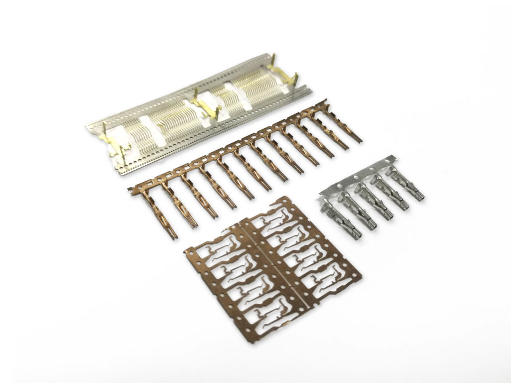
The customer made receptacle terminals for 0.64 mm tab systems, the workhorse contact of automotive wiring. A new vehicle program would add around 60 million terminals a year to an existing volume of 30 million. Their incumbent terminal stamping die, built elsewhere several years earlier, was single-out and ran reliably only at about 600 strokes per minute. At that rate the line would need a second press, a second die and more floor space.
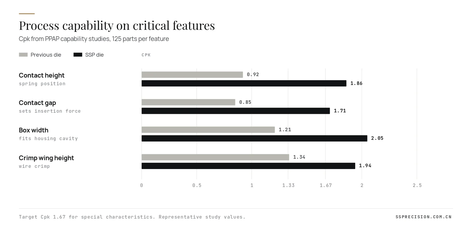
Capacity was only half of the problem. The terminal’s contact spring, the small cantilever that grips the tab, set both insertion force and contact normal force. On the old die, the spring height and the gap between spring and box floor showed Cpk values of 0.85 to 0.92. The end customer required 1.67 on these special characteristics for the new program. Scrap was 2.1%, most of it from sorting on those two features, and the die came off the press for regrinding every 1.5 million strokes.
Requirements for the new terminal stamping die
| Requirement | Target | Why it mattered |
|---|---|---|
| Parts per stroke | 2 | Double output without a second press |
| Stroke rate | 1,200 per minute sustained | Reach program volume on one line |
| Contact height and gap | ±0.02 mm, Cpk 1.67 or better | Insertion force and contact force windows |
| Box width | ±0.03 mm | Fit and retention in the housing cavity |
| Burr | Under 0.01 mm, away from contact faces | Protect the tab plating and the seal |
| Regrind interval | At least 5 million strokes | Fewer die pulls, more uptime |
| Compatibility | Same reel format and pitch direction | Existing crimp applicators and plating lines |
Our approach to the terminal stamping process
We started with the part rather than the die, because most terminal stamping problems begin on the drawing. The customer’s drawing had evolved over years, and a DFM review with their product engineers found three changes that made the process more robust without changing the terminal’s function: a small relief notch at the root of the contact spring to localize bending, a revised coining depth on the contact dimple, and a datum scheme that referenced the box features the housing actually locates on. All three were approved within a week.
Strip layout: two-out on a 36 mm strip
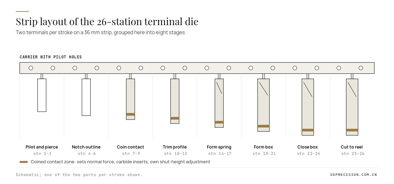
A two-out layout doubles output per stroke, but it also doubles the force imbalance risk and puts two sets of delicate forming stations side by side. We placed the two parts mirrored about the strip centre so cutting and forming loads balanced, and used a single central carrier with pilots at every pitch. Twenty-six stations, grouped into eight stages, take the strip from flat to closed box.
Coining the contact zone before forming
The key decision was to coin the contact spring to its final thickness in its own station, before any bending. Contact force depends on spring thickness cubed, so a small thickness variation from strip tolerance becomes a large force variation. Coining sets the thickness precisely, work-hardens the spring and makes the later forming stations see identical material. The coining inserts are carbide, with their own wedge-adjusted shut height so the toolroom can tune thickness in steps of 2 µm without removing the die.
Forming the spring and box in small steps
On the old die the spring was formed in one hit, and its final height depended on how the strip happened to spring back that day. We split the spring form into three progressive stations with a final set station, and formed the box walls in four stations with a closing station that sizes the box against a hardened mandrel. Each step moves the metal a little, so springback is small and consistent.
Tool materials and die construction
All cutting punches and die inserts are carbide in the 15% cobalt class, profile ground and supported by hardened stripper guides. Forming punches are PM high speed steel with a PVD coating, which suits the pre-tinned strip. The die set uses precision ball-bearing guide posts and a floating lifter system that keeps the strip level at speed. Every station is built from interchangeable inserts, so any worn component can be swapped from stock.
In-die sensing for 1,200 strokes per minute
At 20 strokes per second, terminal stamping leaves no time for an operator to react. The die carries pilot-release sensors for misfeed detection, slug sensors on the piercing stations and a part-out sensor at the cut-off, all wired to the press controller to stop within one stroke. That protects the carbide tooling, which would otherwise be the first casualty of a misfeed.

Terminal stamping project timeline
Speed mattered because the vehicle program dates were fixed. The eleven weeks broke down as follows:
- Week 1: DFM review with the customer’s product engineers, three drawing changes agreed, strip specification drafted with the copper supplier.
- Weeks 2 to 3: strip layout, forming simulation of the spring and box, and the full 3D die design, reviewed station by station with the customer’s toolroom.
- Weeks 3 to 6: machining of plates and inserts in parallel, wire EDM and profile grinding of carbide components, die assembly and sensor wiring.
- Week 7: first strips in our tryout press, T1 samples measured and shipped by air.
- Weeks 8 to 9: fine tuning of lane balance and set stations, capability run at 1,200 strokes per minute, customer run-off in Dongguan.
- Week 10: die shipped with spares and documentation; installation and training on the customer’s press.
- Week 11: production trial run and PPAP submission, approved by the end customer.
Running design review and machining in parallel was only possible because the terminal stamping layout was frozen early and the insert standards were already defined, so plate machining could start before the last forming station was detailed.
Terminal stamping tryout and PPAP
First strips ran in our tryout press in week seven. The contact height came in 0.015 mm high on one of the two lanes, which traced to a difference in lifter height between the lanes; one shim corrected it. By the third tryout day both lanes were within the middle third of tolerance on all critical features.
We then ran capability studies of 125 consecutive parts per lane on the four special characteristics, at 1,200 strokes per minute, measured on an optical measuring system and a contact force tester. The customer witnessed the run-off in Dongguan before the die shipped, and PPAP was approved in week eleven after the production run on their own press.
Terminal stamping results after six months
| Measure | Previous die | SSP die |
|---|---|---|
| Parts per stroke | 1 | 2 |
| Sustained stroke rate | about 600 per minute | 1,200 per minute |
| Net output per hour | about 30,000 | about 138,000 |
| Scrap rate | 2.1% | 0.4% |
| Strokes between regrinds | about 1.5 million | about 6 million |
| Lowest Cpk, special characteristics | 0.85 | 1.71 |
| Sorting operation | 100% optical sort | removed after 3 months of data |
Figures rounded. Net output accounts for scrap and unplanned stops.
The new program volume now runs through terminal stamping on the same press that previously ran the old volume, and the 100% sorting step was removed after three months of stable capability data. The customer keeps a set of spare carbide inserts for every cutting and coining station in stock, which we supply from the original die drawings through our tooling spare parts program.
What made the difference in terminal stamping
Looking back, four decisions carried most of the improvement, and they apply to almost any terminal stamping project:
- Fix thickness before shape. Coining the contact zone first removed the largest source of force variation, strip thickness tolerance, before forming began.
- Form in small, adjustable steps. Several light forming stations plus a set station give consistent springback and a place to tune.
- Balance the strip. A mirrored two-out layout kept loads symmetric, which is what makes 1,200 strokes per minute stable rather than possible.
- Design for maintenance. Insert-based stations and shelf spares turned regrinds into quick swaps and let the die run for weeks without a pull.
None of these ideas is new. What made them work was applying all of them together, from the first DFM meeting to the maintenance manual, and measuring the result at production speed rather than on a handful of hand-picked samples. The same approach now runs on two further dies for the same customer, one for a smaller 0.5 mm terminal system and one for a sealed high current contact, both built around a coined contact zone, balanced strip layouts and interchangeable carbide inserts.
If your current terminal stamping die needs sorting to meet capability, the problem is usually in the process design, not the press. Ask for capability studies on the special characteristics at production speed as part of die acceptance, not only dimensional reports on a few parts.
How the terminal stamping quality plan was built
In terminal stamping, a capable die is only half of a capable process. Together with the customer’s quality team we wrote a control plan that ties each special characteristic to a die feature, a measuring method and a reaction plan. Contact height and gap are measured on an optical system every two hours and at every reel change; box width is checked with a go and no-go gauge at the press; contact normal force is sampled on a force tester once per shift. Every regrind is logged with stroke count, the station, the amount removed and the shim added, so wear trends are visible before they reach the part.
We also delivered the die with a maintenance manual: the order to remove stations, torque values for the insert clamps, the shut-height settings for each coining station and the regrind limits for every carbide component. The customer’s toolroom was trained on the die in our facility during the run-off week. That documentation is what allows a die to keep its capability after the tenth regrind, not just the first.
Plating, reeling and downstream fit
Because the strip was pre-tinned, the die had to protect the plating as well as form the metal. Forming punches were coated and polished to avoid picking up tin, and lubricant was switched to a light evaporative oil compatible with the downstream crimping and the customer’s cleanliness specification. The finished strip is reeled in the same pitch direction and carrier format as before, so the customer’s existing crimp applicators and inspection cameras needed no changes. Keeping the downstream interface unchanged was a requirement from the first meeting, and it saved the customer weeks of applicator requalification.
Strip specification for terminal stamping
A terminal stamping die is tuned to the strip it is tried out on, so strip consistency matters as much as die precision. For this program we agreed a tighter strip specification with the customer’s copper supplier: thickness tolerance of ±0.005 mm instead of the standard ±0.008 mm, a narrower band on yield strength, controlled camber, and slit edges free of burr on the carrier side. Pre-tinned strip was specified with reflowed tin of controlled thickness, because heavy or uneven tin builds up in the forming stations and changes springback.
Each coil arrives with a certificate, and incoming inspection checks thickness across the width and a tensile test per heat. When a coil drifts toward the edge of the yield band, the toolroom has a documented set-station adjustment for it. That link between the coil certificate and the die settings is one of the quiet reasons why terminal stamping capability holds steady from reel to reel.
Cost per thousand terminals
Customers often compare terminal stamping dies on price and lead time alone. For a high volume part, the numbers that matter are cost per thousand terminals and the cost of keeping the process capable. In this project the new die cost more than a like-for-like replacement of the old one, because of the two-out layout, carbide throughout and in-die sensing. Against that, the customer avoided buying a second press and die, removed a sorting operation, cut scrap by four fifths and reduced die pulls from several per week to about one every two weeks. The die paid for itself within the first year of the new program, before counting the value of passing PPAP on time.
Questions to ask a terminal stamping supplier
Whether you buy a die or finished terminals, a few questions reveal how a supplier approaches terminal stamping:
- How is the contact zone thickness controlled, and can it be adjusted without removing the die?
- Which stations are carbide, and are all wear components designed as interchangeable inserts with drawings supplied?
- What in-die sensors are fitted, and are they wired to stop the press within one stroke?
- Will capability studies be run at production speed on your special characteristics before the die ships?
- What maintenance documentation, regrind limits and spare parts list come with the die?
- Can the supplier run the die in its own tryout press at full speed, and can you witness the run-off?
Clear answers to these questions predict how a terminal stamping die will behave after a year of production far better than a price comparison does.
Terminal stamping dies at SSP
We have designed and built dies for connector terminals, lead frames and press-fit pins since 2008. Our progressive die stamping page describes the range of parts and speeds we cover, and the stamping die gallery shows typical tools. For customers who prefer to buy parts, our serial production cell runs terminals on reel. For background on the contacts themselves, see our press-fit pin guide, and for terminal systems in general, the electrical connector overview is a useful primer.
Need more output or capability from a terminal die?Send the terminal drawing, material and target volume. We will reply with a strip layout concept and a quote.
Request a quoteTerminal stamping FAQ
How fast can a terminal stamping die run?
Well built terminal stamping dies for small terminals in thin copper alloy commonly run at 800 to 1,500 strokes per minute on high speed presses. Stable speed depends on strip balance, lifter design, sensing and the press, not only on the die.
Why coin the contact zone of a terminal?
Contact force depends strongly on spring thickness. Coining sets the thickness precisely regardless of strip tolerance, work-hardens the spring and makes the following forming stations consistent.
What Cpk is required for automotive terminals?
Automotive customers commonly require Cpk of 1.67 or higher on special characteristics such as contact height and gap, and 1.33 on other significant features, demonstrated at production speed during PPAP.
What material is used for automotive terminals?
Copper nickel silicon alloys are common for high temperature and high reliability terminals because they combine strength, conductivity and resistance to stress relaxation. Phosphor bronze and brass are used where requirements are lower.
How long does a new terminal stamping die take?
For a die of this complexity, first samples typically take 6 to 9 weeks after design approval, with PPAP support adding 2 to 4 weeks depending on the customer’s process.
Customer name, part number and some figures are anonymized or rounded to protect confidentiality.