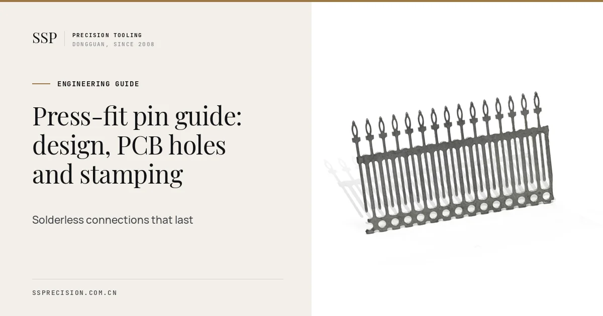
A press-fit pin makes an electrical and mechanical joint with a printed circuit board without a drop of solder. Pushed into a plated through-hole, its compliant zone deforms, loads the copper barrel and forms a gas-tight contact that can survive vibration, heat and twenty years in a car.
That simplicity hides tight engineering. The pin, the hole, the plating and the stamping die all have to agree to within a few hundredths of a millimetre. This guide covers what our die designers and quality engineers check when a customer brings us a new press-fit pin: how the compliant zone works, how to size the PCB hole, what insertion and retention forces to expect, which materials and platings to use, how the pin is stamped, and how it is qualified.
- Most connectors now use a compliant press-fit pin, usually an eye-of-the-needle design, because it keeps insertion force low and protects the hole.
- The PCB hole needs roughly twice the diameter control of a normal plated through-hole: about ±0.05 mm on the finished size, with 25 µm or more of ductile copper.
- A typical 0.64 mm compliant pin inserts at 30 to 80 N and should retain at least 30 N after insertion.
- The compliant zone width is set by coining in the stamping die, so die precision controls force consistency.
- Qualification follows IEC 60352-5, including cross-sections of the hole after insertion.
What a press-fit pin is and why it replaced solder
Press-in technology started in telecom backplanes, where hundreds of pins per connector made wave soldering impractical. It spread to automotive electronics for different reasons: no thermal shock to the board, no solder joints to crack under vibration, no flux residue, and a process that is easy to monitor, because every insertion produces a force curve that can be recorded and judged.
Today a press-fit pin is standard in engine and transmission control units, ABS and airbag modules, EV battery management boards, power converters and server backplanes. A single ECU header can carry 50 to 200 pins pressed in one stroke.
The joint works like a cold weld. As the pin enters, its contact edges wipe the tin or silver on the barrel, break oxide films and press metal against metal at high local pressure. The spring force stored in the deformed zone keeps that pressure on for the life of the product, which is why the contact stays gas-tight and its resistance stays in the sub-milliohm range.
Solid versus compliant press-fit pin designs
There are two families. A solid press-fit pin does not deform; the hole does. A compliant press-fit pin deforms elastically and plastically so the hole does not have to. The table compares them.
| Property | Solid pin | Compliant pin (eye of the needle) |
|---|---|---|
| What deforms | The PCB hole and its copper | Mainly the pin’s two beams |
| Insertion force per pin | High, often 150 to 250 N | Low, typically 30 to 80 N |
| Hole tolerance needed | Very tight | About ±0.05 mm finished |
| Board damage risk | High: cracked barrels, lifted pads | Low when the hole is in spec |
| Rework | Rarely possible | Possible within the standard’s limits |
| Typical use | Thick backplanes, ground pins | ECUs, BMS boards, most connectors |
Compliant zones come in several shapes: the eye of the needle, C-shapes, H-sections and multi-spring designs. The eye of the needle dominates because it is easy to stamp, gives a flat force plateau and centres itself in the hole.
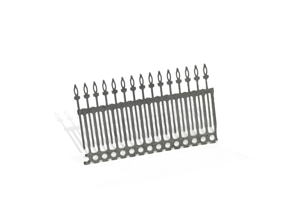
Anatomy of a press-fit pin
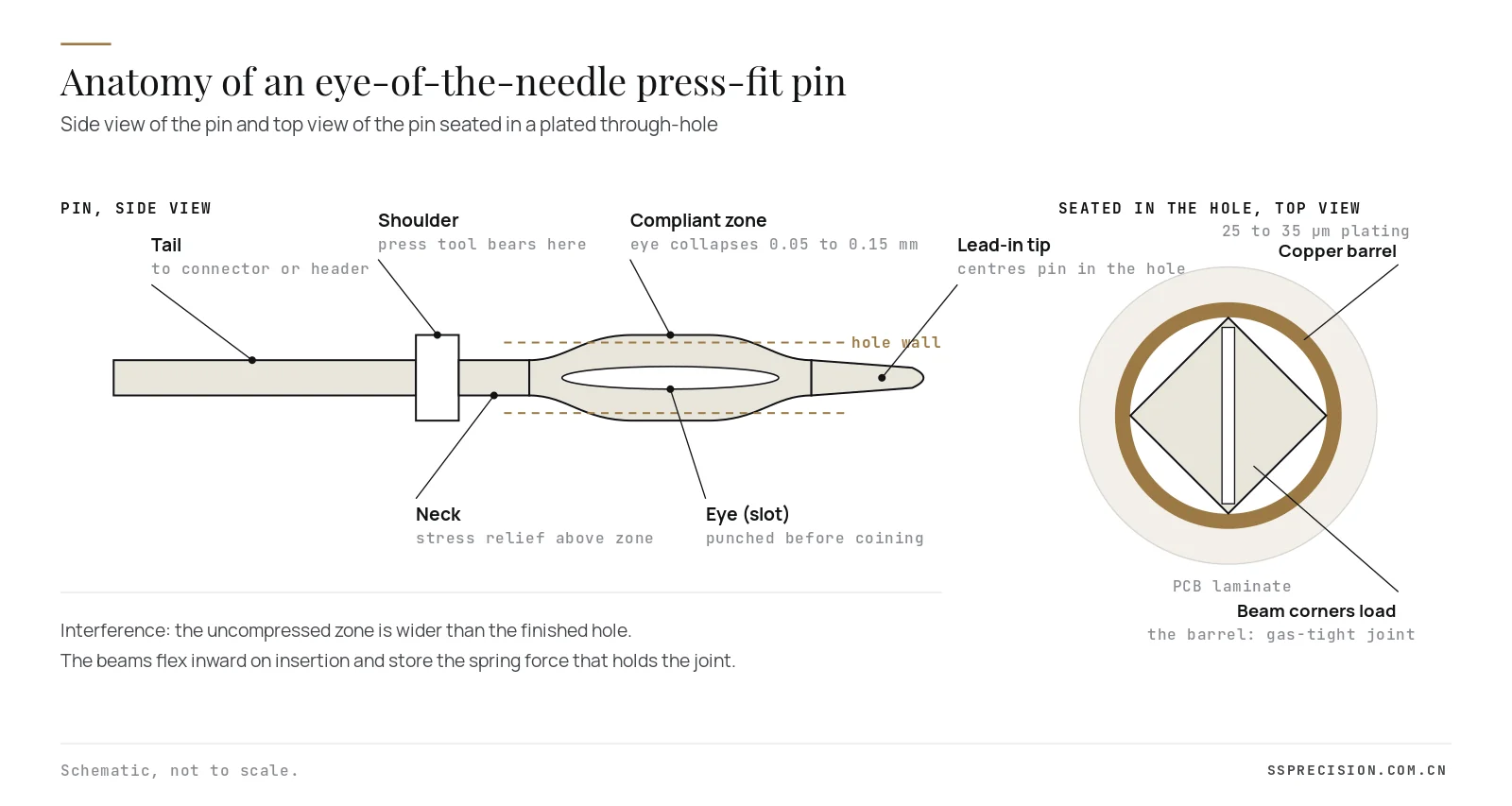
Each feature has a job:
- Lead-in tip: a coined taper that centres the pin and starts deflection gradually, so the first contact does not shave the barrel.
- Compliant zone: two beams separated by the eye. Its uncompressed width, the beam section and the eye length set insertion and retention force.
- Neck: a short, narrower section that stops stress from the compliant zone running into the shoulder.
- Shoulder: the surface the press tool pushes on, and the stop that sets final seating height.
- Tail: the contact end that mates with the connector, often plated differently from the press-in end.
PCB hole design for a press-fit pin
Most press-fit failures start in the board, not the pin. The finished hole must sit in a window narrow enough that the compliant zone is always compressed, but never so far that it cracks the barrel. That usually means a finished hole tolerance of about ±0.05 mm, where an ordinary plated through-hole is allowed ±0.10 mm.
| Pin size | Typical finished hole | Tolerance | Common application |
|---|---|---|---|
| 0.46 mm | 0.70 mm | ±0.05 mm | Fine pitch signal headers |
| 0.61 mm | 0.97 mm | ±0.05 mm | Board-to-board connectors |
| 0.64 mm | 1.02 mm | ±0.05 mm | Automotive ECU and BMS headers |
| 0.81 mm | 1.22 mm | ±0.05 mm | Higher current signal pins |
| 1.02 mm | 1.52 mm | ±0.08 mm | Power and ground pins |
Typical industry values. Always use the hole specification in the connector maker’s application drawing.
Three more board details matter as much as the diameter:
- Copper plating: at least 25 µm average in the barrel, ductile rather than brittle, so it deforms without cracking. Many specifications also set a minimum of about 20 µm at any point.
- Surface finish: immersion tin, OSP and ENIG work well. Hot air solder levelling leaves an uneven thickness in the hole and is a common cause of scattered insertion forces. ENIG also reduces the finished diameter by a few microns, which the drill size must allow for.
- Board thickness and annular ring: 1.6 to 3.2 mm boards are common, with an annular ring of 0.25 mm or more on all layers to spread load and keep inner-layer connections intact.
Insertion and retention forces
Force is the language of press-in assembly. Every pin is pressed with a force sensor on the press ram, and the curve tells the operator whether the pin is good before the board leaves the station.
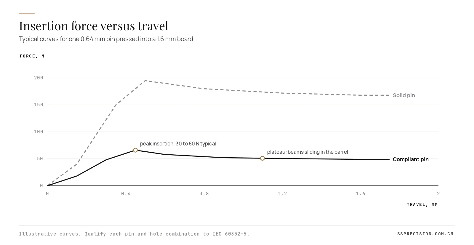
For a 0.64 mm compliant press-fit pin in a 1.6 mm board, insertion force usually peaks at 30 to 80 N, and push-out or retention force after insertion should be at least 30 N. Lower retention means the zone is under-compressed, often from an oversized hole or a zone coined too narrow. Higher insertion force means over-compression, from an undersized hole, thick plating or a zone coined too wide. Both show up on the curve, which is why in-line force monitoring is required by most automotive customers.
Insertion force scatter is mostly a stamping problem. If the compliant zone width varies by 0.02 mm across a reel, force varies by roughly 15 to 25%. That is why we coin the zone in a dedicated station with carbide inserts and measure it on every lot.
Materials and plating for a press-fit pin
The base alloy must be a good spring and a good conductor, and it must resist stress relaxation, because the joint relies on stored force for decades, often at 105 to 150 °C under the hood.
| Alloy | Typical designation | Conductivity | Why it is used |
|---|---|---|---|
| Phosphor bronze | CuSn6, C51900 | about 13 to 15% IACS | Good spring, low cost, general electronics |
| Copper nickel silicon | C70250, C19010 types | about 35 to 50% IACS | High strength and low stress relaxation at temperature; automotive standard |
| Iron-bearing copper | CuFe2P, C19400 | about 60 to 65% IACS | Higher current pins where spring demand is moderate |
| Brass | CuZn30, C26000 | about 28% IACS | Low cost, low temperature, low vibration uses |
Plating is usually a nickel underlayer of 1 to 3 µm to stop copper diffusion, with a thin top layer on the compliant zone. Tin is the most common finish, kept thin, often 0.8 to 1.5 µm and reflowed or annealed to reduce whisker growth and to limit the tin shaved off during insertion. Silver is used on high current and high temperature pins. The tail is often selectively plated with gold for the mating contact.
How a press-fit pin is stamped
A press-fit pin is made in a high-speed progressive die, usually from 0.64 to 1.0 mm strip, at 400 to 1,200 strokes per minute. The strip layout matters: the compliant zone must be coined, not simply blanked, because coining sets the exact width, rounds the contact edges and work-hardens the beams.
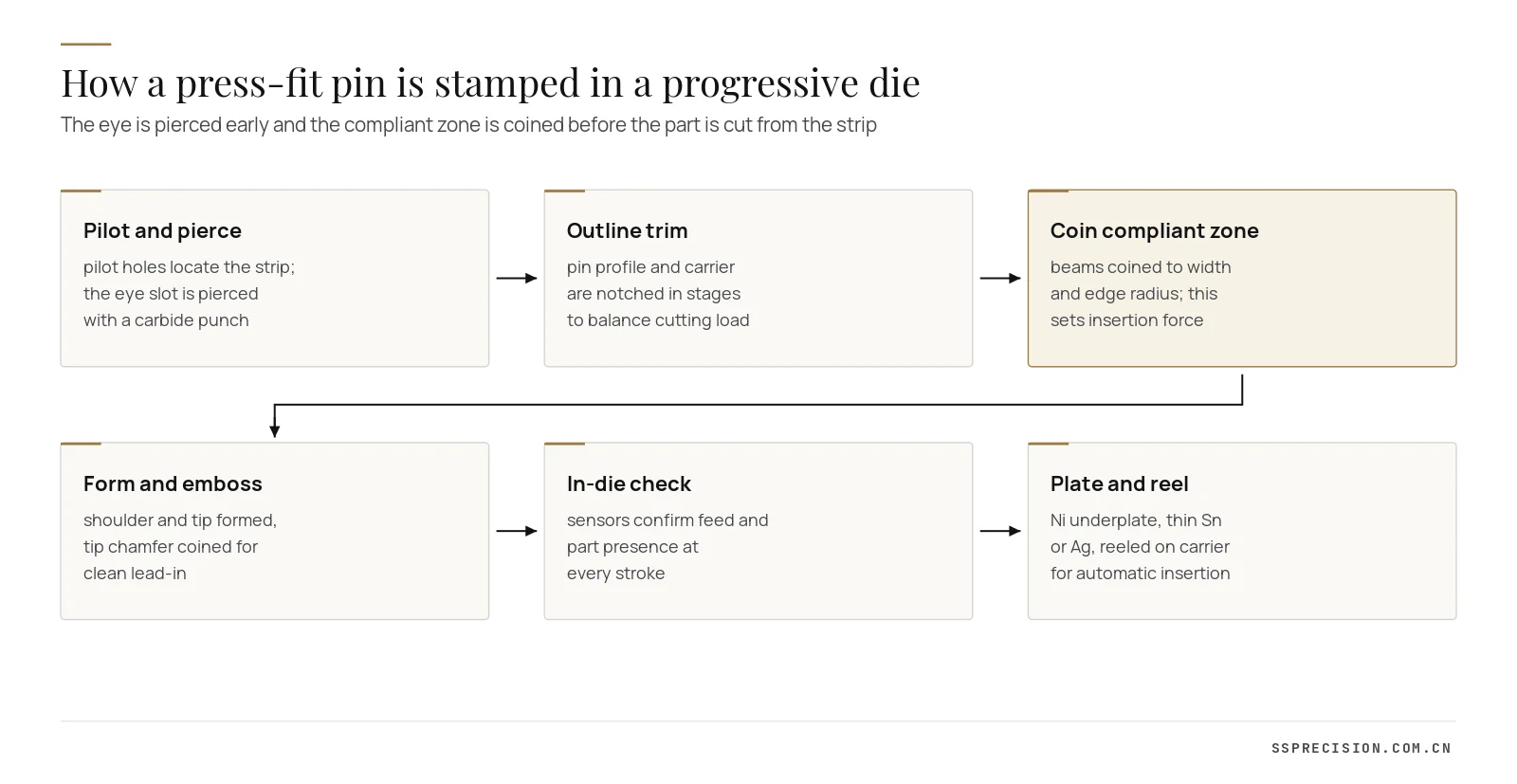
The critical tolerances on a well-built die are tighter than most drawings expect: compliant zone width within ±0.01 to 0.015 mm, eye position within ±0.02 mm, and burr direction controlled so that no burr faces the barrel. Punches and coining inserts for the zone are made from carbide or powder metallurgy steel because their wear directly moves insertion force. Our progressive die stamping line runs these dies with in-die sensors for misfeed and part presence at every stroke.

After stamping, strips are cleaned, plated reel to reel and inspected on an optical measuring system. We measure zone width, eye position and tip geometry on the first, middle and last reel of each lot, and keep the data with the material certificate and plating report.
Qualifying a press-fit pin to IEC 60352-5
The reference standard for press-in connections is IEC 60352-5, and IPC-9797 covers the assembly process. A qualification program for a new pin and hole combination normally includes:
- Insertion force at the minimum and maximum hole sizes.
- Push-out force immediately after insertion and after environmental ageing.
- Contact resistance before and after thermal shock, damp heat and vibration.
- Micro-sections of the hole to check barrel deformation, copper cracks and damage to inner layer connections.
- Repair and re-insertion tests where the product allows rework.
Plan the test boards carefully. Order them with holes deliberately drilled and plated at the minimum, nominal and maximum of the specification, and label each panel. Qualifying a press-fit pin only at nominal hole size proves very little, because production boards will spread across the whole window. For each combination we recommend enough pins to calculate a capability index on insertion and push-out force, typically several dozen per condition, and at least three micro-sections per condition cut through the plane of the beams.
The micro-section is the test customers remember. A good joint shows the barrel wall deformed smoothly by the beam corners, no cracks in the copper and no lifting of the inner-layer connections. A bad one shows copper shaved into a ridge ahead of the pin, a sign of a sharp edge or an oversized zone.
Common press-fit pin failures and their root causes
When a customer sends us a failed board, the symptom almost always points to one of five causes. The table lists what we look for and where the fix usually sits: in the pin, in the die, in the board or in the press.
| Symptom | Likely cause | Where to fix it |
|---|---|---|
| Insertion force above limit | Undersized hole, thick or uneven plating, zone coined too wide | Board supplier drill and plating control; coining insert wear check |
| Low push-out force | Oversized hole, zone coined too narrow, stress relaxation after heat | Hole window; alloy choice for the temperature; die coining height |
| Copper shaved into a ridge | Sharp or burred zone edges, burr facing the barrel, poor lead-in | Coin edge radius, reverse burr direction, re-grind trim punches |
| Cracked barrel or lifted inner layer | Over-compression, brittle copper, thin annular ring | Ductile copper spec, larger annular ring, check zone width |
| Rising contact resistance | Fretting, tin whiskers, contamination in the hole | Thinner reflowed tin or silver finish, cleaner board process |
| Pin leaning or bent after pressing | Tool misalignment, pin not centred by the lead-in, loose carrier | Press tooling alignment, tip geometry, header design |
Two of these are worth expanding. Stress relaxation is the slow loss of spring force when a pin sits at high temperature. A phosphor bronze press-fit pin can lose a large share of its contact force after 1,000 hours at 150 °C, while copper nickel silicon alloys hold far more of it. For under-hood modules that difference decides whether retention is still above the limit at end of life, so alloy choice is a reliability decision, not a cost decision.
Shaving is the other. A blanked edge on the compliant zone acts like a broach. It peels plating off the barrel and leaves loose tin or copper slivers on the board, which can bridge nearby tracks. The fix is in the die: coin the zone edges to a controlled radius and keep the burr on the side away from the hole. That one detail separates a press-fit pin that qualifies first time from one that fails the micro-section.
Is a press-fit pin cheaper than a soldered pin?
Per pin, a press-fit pin costs slightly more than a simple solder pin, because the die needs coining stations and the tolerances are tighter. At assembly level it is usually cheaper. Press-in removes wave or selective soldering, flux cleaning, solder joint inspection and most of the rework loop, and it allows components to be pressed onto boards that already carry heat-sensitive parts. For high pin count connectors on automotive and server boards, the total cost per connection is normally lower, and the reliability data is better.
Nine best practices for a reliable press-fit pin joint
- Freeze the hole specification with the board supplier before the pin design is released.
- Specify ductile copper of 25 µm minimum average in the barrel.
- Avoid hot air solder levelling on press-fit boards.
- Design the lead-in taper and coin the contact edges to a radius; never leave a blanked edge on the zone.
- Coin the compliant zone in a dedicated die station with carbide tooling.
- Control burr direction so no burr faces the barrel.
- Keep top plating thin and whisker-mitigated on the press-in section.
- Record the force curve of every insertion and set limits from qualification data.
- Cross-section holes at the tolerance extremes during qualification, not only at nominal.
Developing a new press-fit pin?Send the pin drawing and PCB hole specification. We will review the compliant zone, propose a strip layout and quote the die and production.
Request a quotePress-fit pin tooling and production at SSP
We have built press-fit and terminal dies for connector makers since 2008, including tools for customers who supply automotive Tier 1s. Our stamping die designs cover the full chain: strip layout, coining stations, in-die sensing and spare inserts for every wear station. When customers want the parts rather than the tool, we run them in our serial production cell and ship plated reels. Pins can also be insert-molded into headers through our over-molding and insert molding service.
For related reading, see our guide to punch and die tolerances and our data on tracking tool wear in progressive dies.
Press-fit pin FAQ
How does a press-fit pin make electrical contact?
The compliant zone is wider than the finished hole. On insertion its beams flex and press their edges against the copper barrel, breaking surface oxides and forming a gas-tight metal to metal contact that is held by the stored spring force.
What hole size does a 0.64 mm press-fit pin need?
A common specification is a finished hole of about 1.02 mm with a tolerance of about ±0.05 mm and at least 25 µm of copper. Always follow the connector maker’s application drawing, because zone designs differ.
What is a normal insertion force for a press-fit pin?
For a compliant 0.64 mm pin, peak insertion force is typically 30 to 80 N, and retention after insertion should be 30 N or more. Solid pins need much higher forces, often 150 to 250 N.
Can a press-fit pin be reworked?
Often yes, within limits. A pressed-out pin should not be re-used, and a hole should generally not be re-used more than a few times. IEC 60352-5 and the connector maker’s instructions define the allowed repair process.
Which standard covers press-fit pin qualification?
IEC 60352-5 defines requirements and tests for press-in connections, including insertion and push-out force, contact resistance, environmental tests and hole micro-sections. IPC-9797 covers press-fit assembly for the board side.