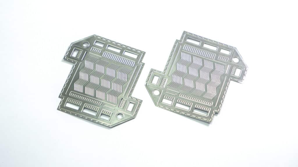
A metallic bipolar plate is one of the hardest parts in sheet metal forming: stainless steel a tenth of a millimetre thick, pressed into hundreds of narrow channels that must hold their depth to a hundredth of a millimetre over the whole plate. This case study describes how our die team took a fuel cell developer’s bipolar plate from cracked prototypes to a stable pilot process.
- Customer
- PEM fuel cell stack developer, commercial vehicle market
- Part
- Anode and cathode bipolar plate halves
- Material
- 316L stainless steel, 0.10 mm, bright annealed
- Active area
- About 300 cm², parallel serpentine flow field
- Tooling
- Two forming dies plus a trim and pierce die per half
- Volume
- Pilot line, 20,000 plates per year, scaling
- SSP scope
- Forming simulation, die design and build, tryout, pilot parts
- Lead time
- First calibrated plates in 10 weeks
Why the customer chose a metallic bipolar plate
In a proton exchange membrane fuel cell stack, the bipolar plate separates one cell from the next, distributes hydrogen and air through its flow channels, carries coolant between the two halves and conducts current. Graphite and composite plates are thick and brittle. A stamped metallic bipolar plate can be under 0.3 mm per cell including both halves, which raises the stack’s power density and makes it rugged enough for trucks and buses.
The price of that performance is manufacturing difficulty. Stainless steel must be formed into very fine channels without cracking, then coated to keep interfacial contact resistance low and corrosion in check. The US Department of Energy’s technical targets for fuel cell components show how demanding the part is:
| Characteristic | DOE target for bipolar plates |
|---|---|
| Cost | $3 per kW net |
| Plate weight | 0.4 kg per kW net |
| Corrosion, anode and cathode | under 1 µA/cm² |
| Areal specific resistance | under 0.01 Ω·cm² |
| Electrical conductivity | over 100 S/cm |
| Forming elongation | 40% |
2020 targets as published by the US DOE Hydrogen and Fuel Cell Technologies Office.
Three problems with the prototype bipolar plate
The customer came to us with plates from a prototype supplier that formed the flow field in a single hit on a hydraulic press. Three problems stopped the design from moving to a pilot line.
Problem one: cracks at the channel corners
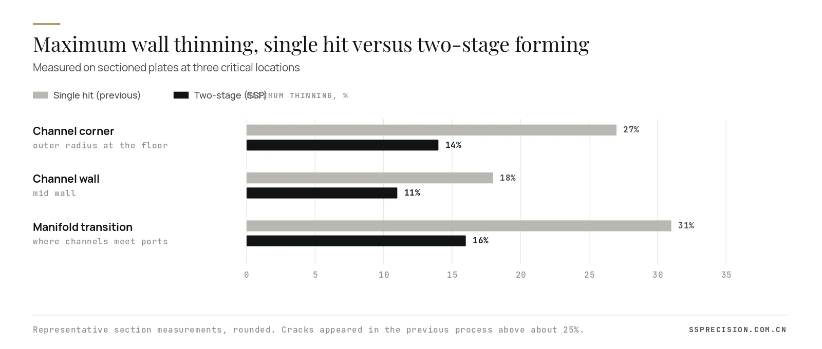
Roughly one plate in eight showed cracks, most of them at the channel floor corners where channels turn and at the transitions where the flow field meets the manifold ports. Sectioned plates showed local thinning of 27 to 31% at those points. Stainless 316L can stretch a long way in a tensile test, but in a narrow channel the strain concentrates at the corners instead of spreading, so a single hit exhausts the material locally.
Problem two: channel depth variation
Channel depth varied by about ±0.03 mm across the plate, deeper in the centre and shallower at the edges. In a stack, that becomes uneven compression of the gas diffusion layer: some areas are over-compressed, which blocks gas flow, and others are under-compressed, which raises contact resistance. The stack developer needed ±0.01 mm.
Problem three: flatness and springback
After trimming, the plates bowed and twisted by up to 0.4 mm as residual stresses from forming released. Two bowed halves cannot be laser welded into a sealed pair without clamping that distorts the flow field, and the pair must lie flat in the stack.
Our approach to the bipolar plate forming process
We began with forming simulation of the full plate rather than a single channel, because the edge and port effects that caused cracking only appear at plate scale. The simulation reproduced the prototype supplier’s thinning pattern within a few percent, which gave us a credible baseline for changes.
Two-stage forming: preform, then calibrate
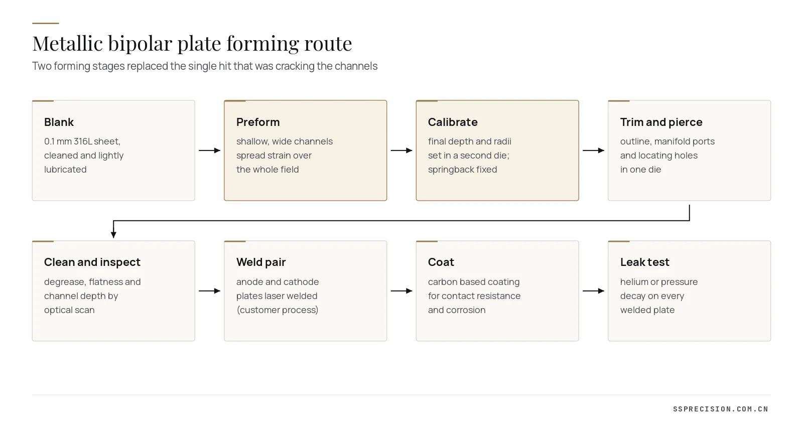
The central change was to split forming into two dies. The preform die makes wider, shallower channels with generous radii, drawing material in from the whole field and from the plate border rather than stretching it locally. The calibration die then forms the final channel depth and radii. Because the metal has already been distributed, the second stage only needs a small amount of additional local strain. Simulation predicted maximum thinning falling from 31% to about 17%, and tryout came in at 16%.
Small geometry changes with large effect
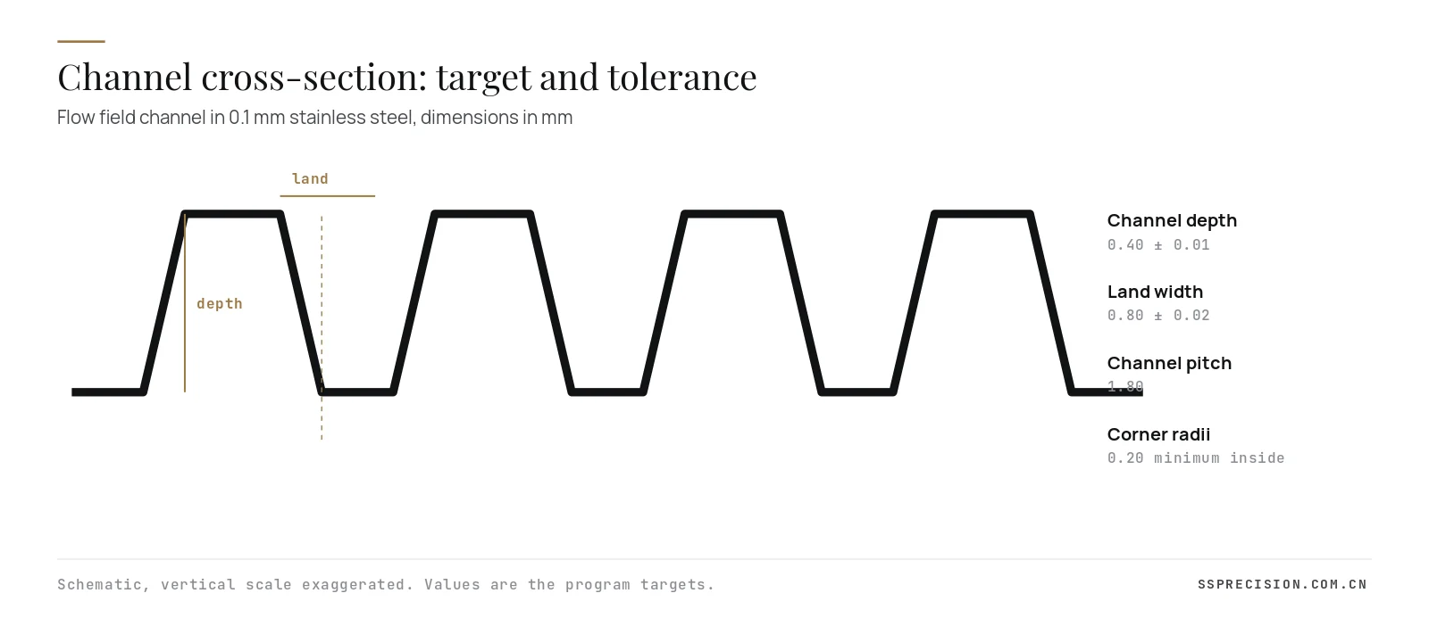
Working with the customer’s stack engineers, we agreed three changes to the bipolar plate design that did not affect flow performance: a minimum inside corner radius of 0.20 mm at the channel floor, a slightly larger draft on the channel walls, and a softened transition between the flow field and the manifold region, where the old design had a sharp step. The customer confirmed with flow simulation that pressure drop and distribution were unchanged.
Die construction for a 0.1 mm part
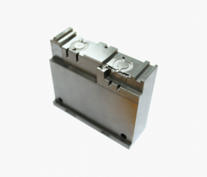
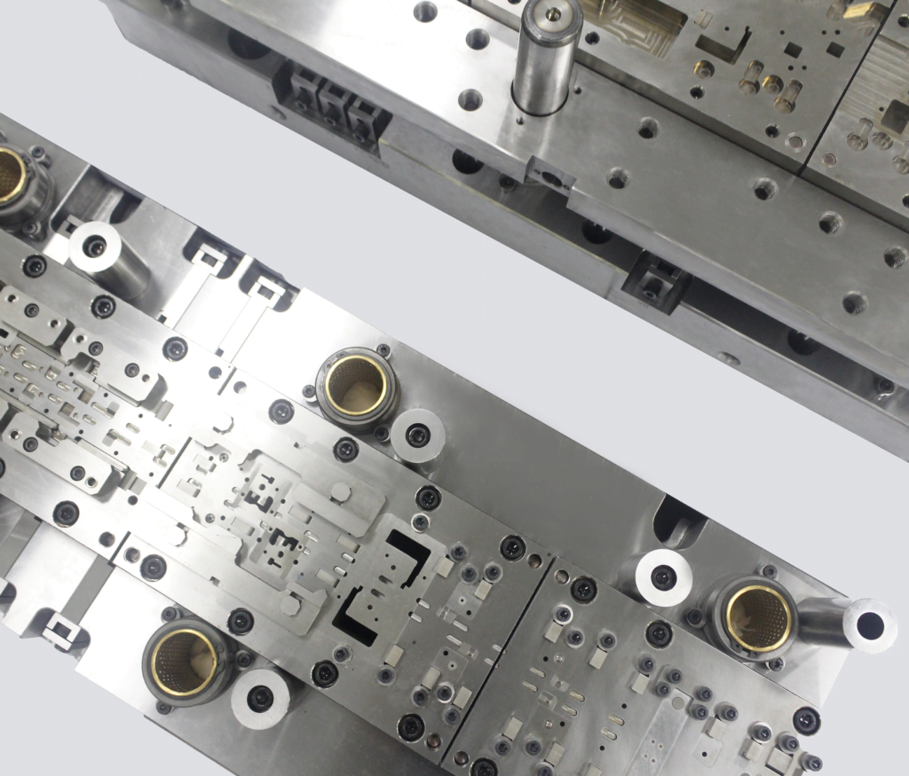
A die for a bipolar plate is closer to a precision mold than to a normal stamping die. The forming inserts were cut by wire EDM and high-speed milling from a powder metallurgy tool steel hardened to around 60 HRC, then polished in the direction of metal flow and PVD coated to prevent galling on the stainless. Punch and die inserts are matched as pairs, with the gap across the field held to within a few microns of the sheet thickness. Four precision guide posts and a very stiff die set keep the halves aligned under load, because any tilt shows up directly as a depth gradient across the plate.
The calibration die also carries a controlled flat border that clamps the plate edge during the last part of the stroke. That border, combined with a short dwell at bottom dead centre on a servo press, sets the stresses in the plate so that it stays flat after trimming.
Lubrication and cleanliness
A bipolar plate is coated after forming, and the coating fails if any residue remains in the channels. We qualified an evaporative forming oil applied in a thin, even film by roller, so the plate could be cleaned with a standard aqueous wash before coating. Lubricant choice also affected thinning: the previous heavy drawing compound had been pooling in the channels and trapping air, which changed local friction and made thinning less predictable.
Why a servo press mattered
The prototype supplier formed the plates on a hydraulic press with a fast approach and no control of speed near the bottom of the stroke. We ran both dies on a servo press programmed with a slow final approach, a short dwell of a few hundred milliseconds at bottom dead centre and a controlled return. The slow approach lets the metal flow into the channels instead of tearing at the first contact, and the dwell relaxes stresses before the load is removed, which reduced springback of the channel walls and helped flatness. The same motion profile will be reproduced on the transfer press for volume production, and it is recorded in the process sheet alongside tonnage and shut height so that every die setting can be repeated exactly after maintenance.
Measuring a bipolar plate
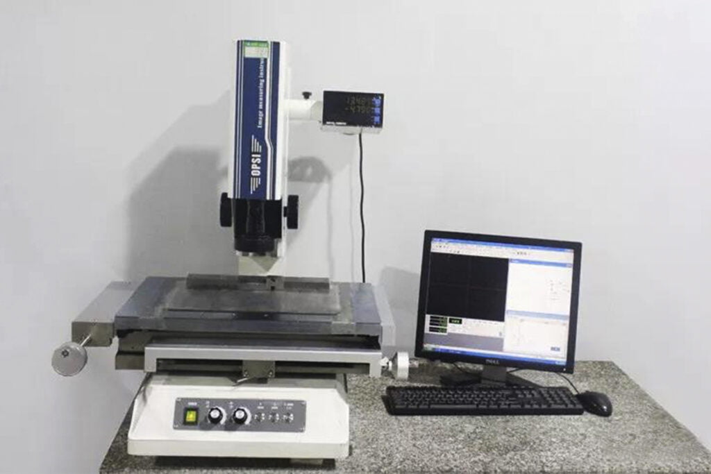
Channel depth over a whole plate cannot be checked with a height gauge. We measured plates on an optical coordinate measuring system scanning 25 zones across the flow field, and sectioned plates at defined locations to measure wall thickness under a microscope. Flatness was measured on a granite plate with the part unclamped. Each tryout loop compared results with the simulation, so the model improved with each iteration.
Bipolar plate results
| Measure | Prototype process | SSP two-stage process |
|---|---|---|
| Cracked plates | about 1 in 8 | none in first 2,000 |
| Maximum thinning | 31% | 16% |
| Channel depth variation | ±0.03 mm | ±0.01 mm |
| Flatness after trim | up to 0.40 mm | under 0.10 mm |
| Laser weld leak test pass rate (customer) | about 85% | over 99% |
Figures rounded. Leak test results reported by the customer from its welding line.
The stack developer has since built several stacks from the pilot plates, and the uniform channel depth showed up as a tighter spread of cell voltages across the stack. The tooling concept, two forming stages and a trim and pierce die per plate half, is now the basis of a transfer die for the volume phase, where the three operations will run in one press at higher speed.
Project timeline
- Weeks 1 to 2: review of the prototype plates, sectioning and thinning measurement, material testing of the customer’s 316L coil, full plate forming simulation of the existing process.
- Weeks 3 to 4: preform geometry developed in simulation, three design changes agreed with the stack engineers, die design released.
- Weeks 5 to 8: insert machining, wire EDM, polishing and PVD coating; die sets built and aligned.
- Week 9: first preform and calibration tryout on a servo press; depth gradient of 0.015 mm corrected by re-shimming one insert pair.
- Week 10: first calibrated plates within all targets, shipped for the customer’s welding and coating trials.
- Weeks 11 to 16: pilot production of 2,000 plates with sampling on every lot, and a joint review of welding and stack results.
Designing for the welding and sealing interface
The two halves of a metallic plate are laser welded together along the perimeter, around the manifold ports and at points across the field, forming a sealed coolant space between them. Welding quality depends on how well the halves meet: a gap of more than a few hundredths of a millimetre along the weld path lets the laser burn through or leaves a weak seam. That turned the flatness requirement from a dimensional nicety into a process necessity.
We therefore defined the weld paths as controlled zones in the forming dies: flat lands with tighter flatness than the rest of the plate and no forming features within a set distance. Locating holes pierced in the trim die, rather than in a separate operation, gave the customer’s welding fixture a consistent reference between anode and cathode halves. Those two details raised the customer’s leak test pass rate more than any change to the welding parameters.
What drives bipolar plate cost
At pilot volumes, tooling and scrap dominate the cost of each plate. At volume, material, press time, coating and inspection take over. Stainless strip at 0.1 mm is not expensive per plate, but the coating can be, and every scrapped plate after coating wastes it. Reducing cracks and flatness rejects before coating is therefore the fastest way to lower cost. On the tooling side, insert-based die construction matters: when a forming insert wears or is damaged, it can be replaced and re-matched without remaking the die set, which protects both cost and delivery in a program where each stack build is scheduled weeks ahead.
From pilot tooling to volume production
Pilot dies are built to learn. Volume dies are built to repeat. For the next phase we are combining preform, calibration and trimming into a single transfer die, with servo transfer fingers designed for a part that weighs only a few grams but must not be touched in the active area. At full volume a bipolar plate program may need millions of plates a year, which changes the economics of every choice: insert steel, coating, lubrication, cleaning and inspection all move from manual to in-line.
Two lessons from the pilot carry directly into that design. The preform geometry, not the final geometry, is where cracking is won or lost, so it must be designed with the same care. And flatness is a product of the forming process, not a trimming problem, so the border clamping and bottom dwell must be preserved in the transfer die.
Lessons for anyone developing a bipolar plate
- Simulate the whole plate early. Cracks at ports and field edges do not appear in single-channel models.
- Plan two forming stages. For 0.1 mm stainless and channel depths around 0.4 mm, a single hit rarely stays below safe thinning at production tolerances.
- Specify radii with forming in mind. A 0.1 mm change to the corner radius can move peak thinning more than any die setting.
- Treat the die like a mold. Insert matching, alignment, polish direction and coating decide depth uniformity.
- Design for cleaning and coating. Lubricant and cleanliness are part of the forming process, not an afterthought.
- Control flatness in the forming die. Border clamping and bottom dwell set residual stress before trimming.
If your bipolar plate is still in design, send us the flow field geometry before it is frozen. A forming review at that stage costs days; changing a proven flow field after stack testing costs months.
Material choices for a metallic bipolar plate
Most metallic plates use 316L stainless steel, as in this project, because it combines formability, corrosion resistance and cost. Some developers choose 304 or ferritic grades for cost, and titanium for the highest corrosion resistance and lowest weight, especially in electrolyzers. Titanium forms very differently: lower elongation, strong anisotropy and a tendency to gall, so a bipolar plate design that works in 316L usually needs larger radii and a revised forming route in titanium. Thickness between 0.075 and 0.1 mm is typical; thinner sheet saves weight but reduces the forming window further.
Coatings, applied after forming and welding, bring the surface to the contact resistance and corrosion targets. Carbon-based coatings, conductive nitrides and precious metal layers are all in use. The forming process affects the coating result: surface scratches, residual lubricant and micro-cracks at thinned corners all create sites where coating adhesion and corrosion resistance suffer. That is one more reason to keep thinning low and to polish die inserts in the direction of flow.
Developing a metallic bipolar plate or electrolyzer plate?Send the flow field model and material. We will review formability and propose a die concept for pilot and volume phases.
Request a quotePrecision forming at SSP
Bipolar plates draw on the same skills as our other precision work: forming simulation, EDM and grinding of hardened inserts to micron tolerances, and tryout with optical measurement. We build the full chain of stamping dies, from single-stage precision forming dies to transfer dies for volume production, and our design and manufacturing team supports customers from early DFM. For related reading, see our guide to springback in metal stamping and our article on deep drawn parts in transfer dies.
Bipolar plate FAQ
What material is used for metallic bipolar plates?
Most metallic bipolar plates use 316L stainless steel between about 0.075 and 0.1 mm thick, coated after forming for contact resistance and corrosion. Titanium is used where corrosion resistance and weight matter most.
Why do bipolar plate channels crack during stamping?
In narrow channels strain concentrates at the corners and at transitions to the manifold area. A single forming hit can thin those points past the material’s limit. Two-stage forming, larger corner radii and softer transitions reduce peak thinning.
How accurate must a bipolar plate be?
Channel depth is typically held to about ±0.01 to 0.02 mm across the plate, with flatness around 0.1 mm, so that the gas diffusion layer is compressed evenly and the welded pair seals reliably.
Is a bipolar plate stamped or hydroformed?
Both are used. Stamping with matched dies is the dominant route for volume production because it is fast and repeatable. Hydroforming and rubber pad forming are used for prototypes and some low volume designs.
What are the DOE targets for bipolar plates?
The US DOE 2020 targets include a cost of $3 per kW, weight of 0.4 kg per kW, corrosion under 1 µA/cm², areal specific resistance under 0.01 Ω·cm² and electrical conductivity over 100 S/cm.
Customer name, part details and some figures are anonymized or rounded to protect confidentiality.