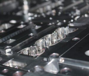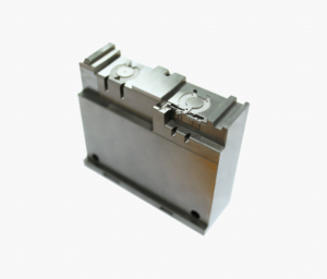
This LSR mold case study follows a medical silicone check valve from a flash-prone 8-cavity tool to a fully automatic 32-cavity cold runner mold. The valve weighs 0.35 g, seals with a lip less than 0.3 mm thick, and cannot carry a trace of flash. The new LSR mold removed manual trimming, cut the cycle time by more than a third and raised output more than six times from one molding cell.
- Customer
- Medical device OEM, infusion and respiratory products
- Part
- Umbrella type check valve, 0.35 g, sealing lip under 0.3 mm
- Material
- Medical grade two-part LSR, 50 Shore A, platinum cure
- Tooling
- 32-cavity LSR mold with cold runner and needle valve gates
- Volume
- About 30 million valves per year
- SSP scope
- DFM, mold design and build, sampling, validation support
- Lead time
- T1 in 9 weeks, validation lots in 14
- Environment
- ISO Class 8 cleanroom molding at the customer
The challenge: flash on a medical seal
Liquid silicone rubber is injected as a low viscosity liquid, thinner than most thermoplastic melts, and it cures in a hot cavity. That low viscosity is what lets LSR fill thin lips and fine details, and it is also what makes it flash through any gap larger than about 5 microns. On the customer’s previous 8-cavity tool, parting line wear and uneven cavity temperatures produced intermittent flash on the valve’s sealing lip. Every valve was inspected under magnification and a share of them was trimmed by hand, which in a medical product is both costly and a validation headache.
Demand was also rising. A new infusion set platform would triple valve consumption, and the customer wanted the whole volume from one press in its cleanroom rather than adding presses and operators. The brief to us was clear: a flashless, fully automatic LSR mold with enough cavities to meet the new volume, and consistent enough to pass process validation without a trimming step.
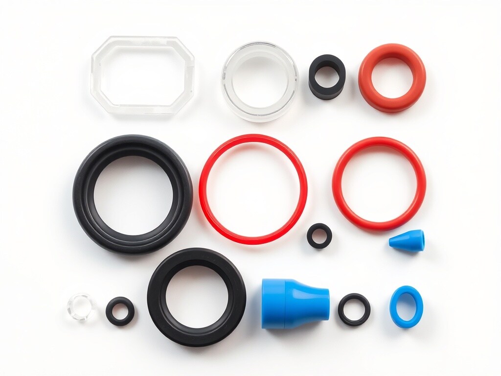
Requirements for the new LSR mold
| Requirement | Target | Reason |
|---|---|---|
| Cavities | 32 | Meet triple volume from one press |
| Flash | None visible at 10x on the sealing lip | Remove manual trimming and its validation risk |
| Runner | Cold runner, no runner waste | LSR runner scrap cannot be reground |
| Cycle time | 25 s or less | Output and cost per part |
| Weight consistency | ±1% cavity to cavity | Opening pressure of the valve |
| Demolding | Fully automatic, no operator contact | Cleanroom handling and throughput |
| Traceability | Cavity number moulded on each part | Medical device lot and cavity tracking |
Our LSR mold design approach
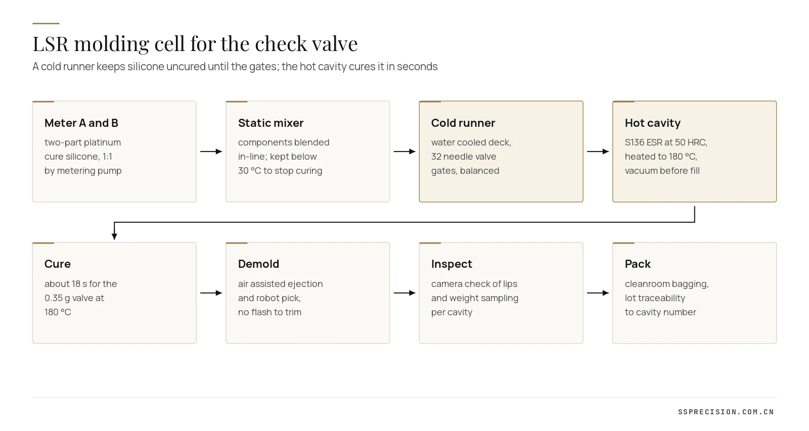
An LSR mold works upside down compared with a thermoplastic mold. The material enters cold and must stay cold until it reaches the cavity, then it must heat and cure as fast as possible. That means two thermal zones side by side in one tool: a cold runner deck at around 20 °C and a cavity plate at 170 to 190 °C, separated by insulation so that neither disturbs the other.
Cold runner and needle valve gates
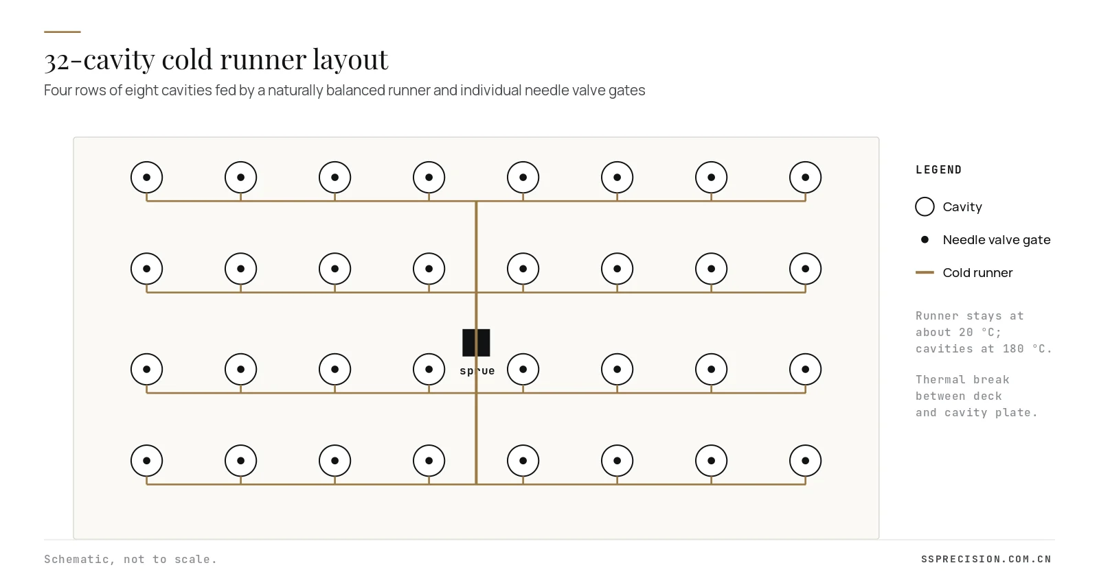
We designed a naturally balanced cold runner, with every cavity the same flow length from the sprue, and fitted each cavity with a pneumatically actuated needle valve gate. The needles shut off flow at the end of fill, so there is no runner to cure and no gate vestige beyond a small, smooth witness on the non-functional face. Needle timing is adjustable by cavity group, which allowed us to fine-tune fill balance during sampling.
A flashless parting line
Flash control in an LSR mold is a matter of microns. We held parting line flatness and cavity insert heights to within ±0.003 mm, ground the shut-off faces as matched pairs, and designed the cavity plates thick enough that they do not deflect under injection pressure. The sealing lip itself was placed away from the parting line, with the parting line on a thicker section where any micro-gap would be harmless.
Venting in LSR is tricky, because a vent large enough to let air out also lets silicone out. Instead of vents, the mold uses a vacuum system that evacuates the cavities in the moment before injection, sealed by an O-ring around the cavity plates. Air traps and burn marks at the end of fill disappeared, and the parting line stayed shut tight.
Steel, heating and temperature uniformity
Cavity inserts are S136 ESR stainless tool steel hardened to about 50 HRC, chosen for polishability, wear resistance at the shut-offs and resistance to the cleaning agents used in the cleanroom. Our mold steel guide explains why stainless is the default for medical silicone. The cavity plates are heated by cartridge heaters in four zones with their own thermocouples, so the temperature across 32 cavities stays within about ±2 °C. Uneven temperature was the root cause of the weight variation on the old tool, because hotter cavities cure earlier and pack less.
Automatic demolding
Silicone is soft and sticky, and a thin valve cannot be pushed off with ejector pins without damage. The valve seats on a core with a light surface texture; air blast lifts it free and a robot with a soft gripper picks the full shot of 32 parts into a tray that keeps them separated by cavity. The cavity number is moulded into each valve, so any defect can be traced to one cavity without sorting whole lots.
Material behaviour that shaped the design
Two-part platinum cure silicones start to react as soon as the A and B components meet. At room temperature the pot life is long enough for the mixer and runner, but it shortens quickly as temperature rises, so the cold runner deck is water cooled and insulated from the hot cavity plate by a thermal break of low conductivity plates and air gaps. If heat leaks into the runner, silicone starts to cure in the nozzles, gates stick and fill becomes uneven. We modelled the heat flow between the two zones before machining and placed cooling so the runner stays within a few degrees of its setpoint even at the 180 °C cavity temperature.
The chosen grade also has a low viscosity and a fast cure profile, which suits thin lips but punishes any delay in the cycle. Injection speed was set to fill the lips quickly before surface skinning, followed by a short hold that compensates for the thermal expansion of silicone as it heats. Unlike thermoplastics, silicone expands in the hot cavity, which is why an LSR mold needs so little packing and why excess hold pressure produces flash rather than better parts.
Sampling and validation
First shots ran in week nine on a 50-ton LSR press in our sampling cell. Fill was complete in all cavities from the first shot; two cavities at the ends of the outer rows ran slightly light, which a small adjustment of needle opening time corrected. By the third sampling day, cavity weights were within ±0.4% and there was no flash visible at 10x on any lip.
We then supported the customer’s process validation. The mold ran a design of experiments on cavity temperature, cure time and injection speed to define the operating window, followed by capability runs on valve opening pressure, lip thickness and overall height. The customer completed installation, operational and performance qualification in its cleanroom in week fourteen.
LSR mold results
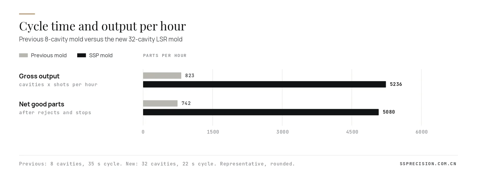
| Measure | Previous 8-cavity mold | SSP 32-cavity LSR mold |
|---|---|---|
| Cycle time | 35 s | 22 s |
| Gross output per hour | about 820 | about 5,240 |
| Flash-related rejects | 4.5% | 0.2% |
| Manual trimming | required on part of every lot | eliminated |
| Cavity weight spread | ±1.5% | ±0.4% |
| Runner waste | none (cold runner) | none (cold runner) |
| Operators per shift on the cell | 1 plus trimming staff | shared, one per several cells |
Figures rounded from customer production data after three months.
The cycle time gain came mainly from the uniform cavity temperature, which allowed a shorter cure without under-cured cavities, and from the automatic demolding, which removed operator variation from the cycle. Removing trimming changed the cost of each valve more than the extra cavities did.
Project timeline
- Weeks 1 to 2: part and material review, filling simulation for LSR, moving the parting line off the sealing lip, cavity number marking agreed.
- Weeks 2 to 4: mold design, cold runner and valve gate layout, thermal design of the deck and cavity plates, customer design review.
- Weeks 4 to 8: machining, hardening and grinding of inserts, polishing, assembly, vacuum and heater wiring.
- Week 9: T1 sampling, needle timing balance, first article inspection.
- Weeks 10 to 12: design of experiments and capability runs, mold shipped with spare cavity inserts and needle sets.
- Weeks 13 to 14: installation and qualification in the customer’s cleanroom.
Measuring a silicone valve
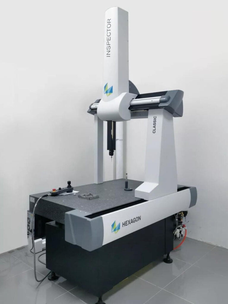
Soft parts deform under a contact probe, so dimensional inspection used non-contact methods: an optical measuring system for the lip thickness and outer diameter, and a coordinate measuring machine with an optical sensor for the valve height relative to the stem. Functional testing, the opening pressure of each valve, was sampled per cavity on a pressure bench. Weight, measured on a precision balance by cavity, turned out to be the quickest early warning of drift, so it became the primary in-process check.
Lessons for your next LSR mold
- Keep the parting line off functional surfaces. Moving the parting line away from the sealing lip made flash harmless even before the tooling was improved.
- Hold shut-offs to microns. LSR flashes at gaps of about 5 microns; matched grinding and stiff plates are not optional.
- Use vacuum rather than vents. Evacuating the cavities before injection removes air traps without creating flash paths.
- Engineer temperature uniformity. Zoned heating with its own control gives consistent cure, consistent weight and a shorter cycle.
- Design demolding with the part. For thin silicone parts, air assist and robot handling beat ejector pins.
- Build in traceability. Cavity numbers on each part make validation and complaint investigation much easier.
If your current silicone part needs trimming or 100% visual sorting, the mold is usually the place to fix it. Send the part model and current reject data, and we will tell you which of these measures would apply.
Open runner or cold runner LSR mold?
Not every silicone part justifies the tooling in this project. The table compares the two common runner concepts for an LSR mold.
| Factor | Open runner | Cold runner with valve gates |
|---|---|---|
| Tooling cost | Lower | Higher: cooled deck, needles, actuation |
| Material waste | Runner cures and is scrapped every shot | None; material stays liquid in the runner |
| Gate vestige | Needs trimming or a tab gate | Small, clean witness mark |
| Automation | Runner must be removed with the parts | Parts drop or are picked individually |
| Best for | Prototypes, low volume, large parts | High volume, small parts, medical and clean parts |
For this valve, runner scrap on an open runner LSR mold would have been several times the part weight on every shot, at medical silicone prices. That alone justified the cold runner at the program volume.
Maintenance plan for a high cavitation LSR mold
A 32-cavity tool runs millions of cycles a year, and its performance depends on keeping shut-offs, needles and seals in condition. We delivered the mold with a maintenance plan built around cycle counts: needle tips and seals inspected every 250,000 cycles and replaced from the spare kit when worn, parting line faces cleaned of silicone film every shift with a non-abrasive method, vacuum seals checked weekly and heater and thermocouple readings logged continuously. A cavity whose weight drifts is taken out of service by closing its needle, so production continues on 31 cavities while the insert is serviced. Designing the LSR mold so a single cavity can be isolated and swapped without removing the tool from the press was one of the customer’s own requirements, and it has already paid off twice.
Design guidelines for silicone valves and seals
- Keep sealing lips on one side of the parting line and let the parting line fall on a thicker, non-sealing section.
- Allow generous radii where the lip meets the body; silicone tears at sharp internal corners during demolding.
- Plan for shrinkage of roughly 2 to 3.5% depending on grade and post-cure, and confirm it with sample parts before final cavity sizing.
- Specify whether post-cure is required; it changes shrinkage, hardness and the extractables profile.
- Agree cosmetic and flash criteria in writing, with magnification and lighting defined, before the LSR mold is built.
Integrating the mold into a cleanroom cell
The cell runs in an ISO Class 8 cleanroom, so the mold was designed to limit particles and simplify cleaning: no grease on exposed moving parts, sealed actuators for the valve gates, and a surface finish on non-molding faces that does not trap silicone film. The robot places parts directly into cavity-separated trays that pass through a pass-box into packing, so parts are never touched by hand between the cavity and the bag.
Cost and payback
A 32-cavity cold runner LSR mold with valve gates and zoned heating costs several times an 8-cavity open runner tool. For this customer the payback came from three sources: the second and third presses that did not need to be bought or validated, the trimming and sorting labour that disappeared, and the lower reject rate. At the program’s volume the mold paid for itself within its first year of production. For low volume parts the balance is different, and a smaller cavity count or a simpler runner may be the better investment, which is exactly the kind of trade-off we lay out in a quotation.
Planning an LSR mold for a medical or sealing part?Send the part model, material and annual volume. We will propose a cavity count, runner system and budget within one business day.
Request a quoteLSR mold building at SSP
We design and build molds for silicone valves, seals, gaskets, membranes and overmolded parts, from prototype tools to high cavitation cold runner systems. Our liquid silicone rubber molding page covers materials and part types, and our injection mold and micro molding pages cover the thermoplastic side. For background reading, see our article on industrial LSR injection molding and the general introduction to liquid silicone rubber.
LSR mold FAQ
How is an LSR mold different from a plastic injection mold?
An LSR mold is heated, typically to 170 to 200 °C, to cure the silicone, while the runner is kept cold so the material does not cure before the cavity. Shut-offs must be far tighter because liquid silicone flashes through gaps of about 5 microns.
What is a cold runner in LSR molding?
A cold runner is a cooled manifold that keeps silicone below its cure temperature until it reaches the gate. Combined with valve gates, it eliminates runner waste, which matters because cured silicone cannot be reground.
How do you prevent flash in an LSR mold?
By grinding shut-off faces to within a few microns, using stiff plates that do not deflect, placing parting lines on non-functional sections, evacuating cavities with vacuum instead of vents, and keeping cavity temperature uniform.
What steel is used for an LSR mold?
Hardened stainless tool steels such as S136 ESR at about 50 HRC are common for medical and food contact silicone parts, because they polish well, resist wear at shut-offs and tolerate cleaning agents.
How many cavities can an LSR mold have?
Small parts such as valves and seals often run in 16 to 64 cavities, and very small parts in more. The right number depends on part size, volume, press size and how well the runner and temperature can be balanced.
Customer name, part details and some figures are anonymized or rounded to protect confidentiality.