A one-sided burr on a pierced feature is a reason to investigate local cutting conditions before regrinding the entire tool. In this worked case, an assumed lateral offset changes a nominally symmetric punch-to-die gap into a tight side and an open side. The engineering task is to separate alignment, edge damage, stock variation and dynamic movement, then qualify a correction under production conditions.
Case study basis
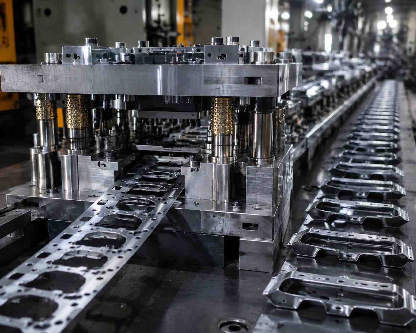
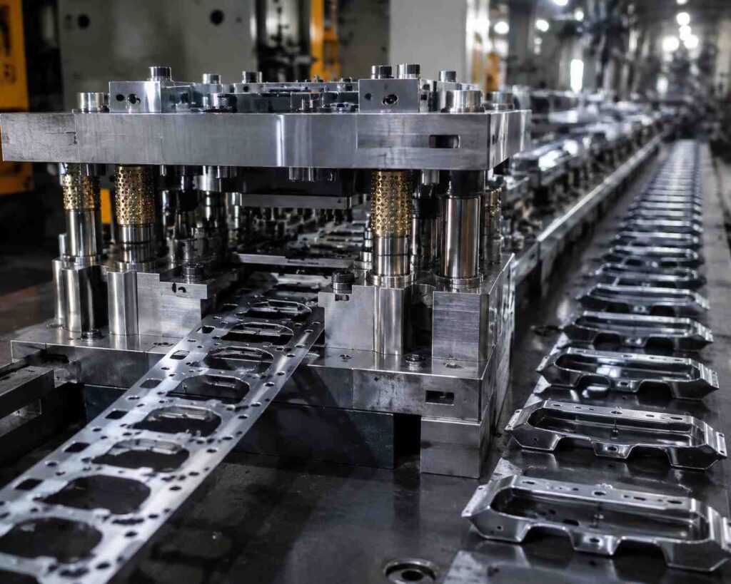
This is an illustrative engineering case study, not a report of an SSP customer project. All dimensions and findings used in the worked scenario are stated assumptions. No customer identity, achieved burr reduction, production saving or measured SSP result is claimed. Existing site images explain the tooling context; they do not document this example.
The scenario addresses a pierced hole in a progressive stamping tool after a maintenance intervention. It is useful for process engineers, toolmakers and quality teams because the visible defect can have several causes. A burr is evidence to interpret in context, not proof that the tool steel, nominal clearance or entire die design must be replaced.
Key takeaways
- Define the location and face of the one-sided burr before any cleaning, deburring or sharpening changes the evidence.
- Compare opposite edge sectors, matched slugs and time-ordered samples rather than averaging the perimeter.
- Distinguish total diametral clearance from clearance per side, and account for eccentricity.
- Correct the verified source of relative movement; centering a static tool is insufficient if it shifts during cutting.
- Release against drawing-specific edge, dimension and functional requirements, then monitor recurrence.
In this case study
Scenario: a one-sided burr after punch replacement
Assume a 1.00 mm sheet is pierced with an 8.00 mm round punch inside an 8.16 mm die opening. The drawing in this example limits burr height to 0.05 mm and also controls the hole’s size and location. Those values define this educational case only. They are not a recommended clearance or tolerance for a particular material, and the geometry does not predict actual burr height by itself.
The constructed scenario has three observations: the nonconforming burr is concentrated in one edge sector, the change appears after punch replacement, and an unloaded dimensional check indicates a lateral offset. Those assumptions make alignment a strong investigation path. They do not eliminate damage, tool deflection, stock differences or a measurement error, all of which remain in the verification plan.
| Item | Assumption in this case | Why it matters |
|---|---|---|
| Operation | Piercing an internal round feature in a progressive die | The pierced hole is retained and the slug is scrap |
| Sheet thickness | 1.00 mm nominal | Clearance ratios depend on actual thickness |
| Punch diameter | 8.00 mm | Defines the nominal punch geometry, not a guaranteed finished-hole size |
| Die opening | 8.16 mm | Gives 0.16 mm nominal diametral clearance |
| Permitted burr | 0.05 mm maximum by the assumed drawing | Acceptance belongs to this example, not a universal standard |
| Maintenance event | A replacement punch was installed | Creates a change point to investigate |
| Assumed offset | 0.035 mm in one lateral direction | Creates unequal local gaps in the simple geometric model |
Illustrative case inputs. No values in this table are presented as measured SSP production data.
The reader’s decision is whether to regrind immediately or preserve the evidence and investigate why the edge changed. Regrinding may be necessary when the edge is damaged, but it also removes material and changes geometry. If the main problem is relative position, sharpening alone can leave the mechanism intact and consume the tool’s remaining service allowance.
Check 1: contain the product and preserve orientation
When the one-sided burr exceeds the actual drawing requirement, follow the plant’s containment procedure. Identify the last accepted check, segregate the affected production interval and retain its material and process traceability. The containment boundary should follow evidence, such as lot identifiers, coil changes, counter readings and inspection records, rather than an assumed shift boundary.
Retain parts as stamped before deburring, cleaning or handling alters the edge. Mark feed direction, punch-entry face and the suspect sector. Use a consistent clock-face or drawing-coordinate convention so inspection, toolroom and production teams refer to the same location. Record the identification on photographs and sample containers; a close-up without orientation is difficult to use in a root-cause comparison.
Preserve time order as well as geometry. Compare samples from before maintenance, after replacement and after any approved adjustment, if those samples exist. Record which are retained production samples and which are new trial pieces. If the pre-change condition is undocumented, keep that uncertainty in the investigation rather than reconstructing a convenient baseline.
Tool access, measurement inside a die and corrective work belong to qualified personnel under the plant’s isolation, stored-energy and machine procedures. The investigation should never depend on reaching into an operating die or intentionally running with a suspected interference. Use approved diagnostic methods and machine settings; a technical article is not a substitute for the press or tooling instructions.
Check 2: measure the one-sided burr consistently
Agree what the drawing means by burr height, which face is inspected and how the base surface is established. Burr height, rollover, fracture roughness and a bent edge are different measurements. A caliper that bridges the feature may be unsuitable for a narrow protrusion. Choose a qualified optical, profilometric or other appropriate method that resolves the required edge geometry.
Use labeled sectors around the feature and report the local maximum as well as its position. Repeat measurements at the suspect sector to assess whether sample placement or edge orientation changes the result. The purpose is to determine whether the difference between sectors is real enough to guide the investigation, not to collect impressive-looking decimal places.
| Measurement record | Recommended content | Avoid |
|---|---|---|
| Feature identity | Drawing feature, face and sample orientation | An unlabeled photograph of a sharp edge |
| Height definition | Reference surface, measurement direction and local maximum | Combining rollover and burr into one value |
| Sector map | Consistent positions around the edge | One average hiding a local maximum |
| Measurement method | Instrument, magnification or settings, calibration status | Reporting resolution as measurement certainty |
| Sample traceability | Part, coil, time and process condition | Mixing production and trial samples |
| Repeatability check | Repeated placement and operator comparison where appropriate | Treating a one-off reading as conclusive |
An evidence record for one-sided burr measurement. Adapt the method to the actual feature and acceptance requirement.
A maximum-only burr requirement is one-sided statistically. Do not invent a lower limit of zero just to report a conventional two-sided Cpk. If capability evidence is required, use a suitable upper-side or other justified method after confirming stability and the measurement system. NIST’s capability guidance explains why statistical assumptions matter before indices are interpreted.
Check 3: inspect cut edges and matched slugs
Examine the part edge and the slug together when traceable slugs can be collected through an approved procedure. Compare corresponding sectors for rollover, burnish, fracture and burr. A change around the perimeter is more informative than a generic statement that the cut looks rough. Document local chipped edges, adhered material or signs of repeated rubbing before cleaning removes them.
Mate Precision Technologies explains in its die-clearance guidance that slug appearance can help assess clearance, tool angularity and dullness. Use that principle as diagnostic context, while recognizing that punch-press tooling guidance does not prescribe every progressive-die application. A single edge image cannot independently prove the mechanism.
Do not automatically label the sector with the largest burr as the widest gap without corroborating geometry. Burr formation also depends on material behavior, edge radius, local damage and the cutting process. The relevant question is whether edge appearance, dimensional checks and timing all support the same explanation. Conflicting evidence should expand the investigation rather than be discarded.
Distinguish common evidence patterns
| Pattern | Candidate mechanism | Discriminating check |
|---|---|---|
| Burr concentrated in one sector | Eccentricity, local wear, edge damage or relative movement | Sector-specific geometry and condition inspection |
| Burr grows across the whole perimeter | General wear, process change or unsuitable clearance | Time trend, complete edge inspection and stock comparison |
| Abrupt change after maintenance | Assembly, seating, replacement geometry or altered entry | Compare the changed interfaces and maintenance record |
| Defect changes with speed or loading | Dynamic guidance, support, strip control or press behavior | Qualified trials and load-sensitive inspection |
| Defect tracks a coil change | Thickness, mechanical properties, surface or lubrication change | Traceable stock and supplier data comparison |
| Raised mark away from the cut edge | Trapped debris, slug-related marking or surface handling | Inspect mark location, scrap path and handling |
Candidate mechanisms are hypotheses. Each requires evidence before selecting a corrective action.
Check 4: calculate local clearance, not just an average
For the idealized concentric round geometry, clearance per side c is half the difference between the die opening Dd and punch diameter Dp: c = (Dd − Dp)/2. Here c = (8.16 − 8.00)/2 = 0.08 mm. Relative to the assumed 1.00 mm thickness, that is 8% per side. Total diametral clearance is 0.16 mm, or 16% of thickness.
Those descriptions are consistent, but confusing them doubles or halves the specified gap. Every drawing and inspection record should identify whether its value is per side or total. State where the dimension is evaluated and at what tool condition. A roundness, taper or positional error can make a nominal diameter difference an incomplete description of the local cutting gap.
Worked one-sided burr clearance calculation
Assume parallel circular profiles and a lateral offset e of 0.035 mm along one diameter. Along that direction, the near-side gap is c − e = 0.045 mm and the opposite gap is c + e = 0.115 mm. Their mean remains 0.080 mm. This is why a correct nominal diameter difference or average gap can coexist with significant local asymmetry.
| Geometric condition | Near-side gap | Opposite gap | Mean of opposite gaps |
|---|---|---|---|
| Ideal concentric model | 0.080 mm | 0.080 mm | 0.080 mm |
| Assumed 0.035 mm offset | 0.045 mm | 0.115 mm | 0.080 mm |
| Ratio to assumed 1.00 mm stock | 4.5% | 11.5% | 8.0% |
Calculated geometry only. These numbers do not predict burr height or establish a material-specific optimum.
The model demonstrates sensitivity to position; it does not reproduce a complete die under load. Real profiles may have runout, taper, damage or elastic deflection. Guidance and press movement may change the gap during cutting. Evaluate the actual tool with qualified inspection methods and preserve the distinction between unloaded dimensions, calculated local gaps and verified operating behavior.
Do not turn the example’s 8% into a design rule. Dayton Lamina’s perforating-clearance discussion shows that burr behavior can be non-monotonic as clearance changes and that material, hole size and slug control matter. The appropriate clearance needs application-specific engineering and trials against the required hole and edge quality.
Check 5: find the source of relative movement
In the constructed case, the assumed offset appears after a replacement punch is installed. Check the seating surfaces, retainer bore, replacement geometry, locating features and the assembled position of the mating die opening. Review whether a spacer, shim or orientation-dependent component was changed. Compare against released dimensions and prior assembly records where they are available.
A punch can be correct individually but incorrectly located in the assembly. Likewise, an accurately machined die insert can move if its mounting fit, seating or support has changed. Separate component conformity from assembly conformity. A replacement-part inspection report should identify the locating datums and critical interfaces, not only the diameter of the working tip.
Review guidance and support through the cutting portion of travel. Worn guides, an unsuitable unsupported punch length, stripper movement or inadequate backing can allow relative displacement. Dayton Lamina’s problem-solving guide specifically includes die and press alignment among checks for punch wear and galling. That supports checking the assembly and machine before selecting a steel upgrade.
Use an evidence matrix before declaring root cause
| Hypothesis | Evidence supporting it | Evidence that challenges it |
|---|---|---|
| Replacement punch seating error | Change coincides with replacement; a positional discrepancy is found | Verified seating and location match the released assembly |
| Guide or support movement | Observed play or load-related relative displacement | Guidance is within specification and the pattern persists unchanged |
| Local cutting-edge damage | Damage and defect align in the same sector | Qualified inspection finds no corresponding edge damage |
| Material or lubrication change | Defect follows a traceable stock or lubricant change | Approved comparison stock reproduces the same sector pattern |
| Measurement artifact | Readings vary strongly with placement or interpretation | Repeated qualified measurements confirm the same local maximum |
The worked case assumes an offset; a real project must establish which mechanism creates it.
The one-sided burr investigation is strongest when the timing, feature location, measured geometry and controlled correction agree. Finding one plausible defect is not the same as proving the complete cause. If several interfaces are changed together, record that limitation: the trial may demonstrate an acceptable combined correction without identifying the contribution of each change.
Check 6: separate tooling effects from stock and process
Review actual stock thickness at relevant locations, material grade and batch, surface condition, lubricant and recent supply changes. A certificate confirms specified properties under its stated scope; it does not by itself describe every local forming condition. Use traceable production data and approved comparative samples to decide whether a stock change is significant.
Review feed setup, strip support, pilot function, press settings and the timing of cutting operations. A progressive die subjects the strip to multiple operations, so movement introduced elsewhere can affect a piercing station. Distinguish a repeating defect fixed to one tool sector from a defect that changes with strip position, feed conditions or an upstream operation.
Change only what the qualified trial plan permits, and keep a record of each condition. Preserve material, lubricant, stroke counter and inspection timing. A low-speed trial can confirm basic motion, but it cannot automatically release high-speed production. If the one-sided burr returns only under production loading, treat that as new evidence of a load-dependent mechanism rather than proof that the first repair was complete.
For related subjects, use the existing SSP guide to general progressive-die troubleshooting and the article on tracking progressive-die wear. This case remains focused on asymmetric edge evidence and local clearance; those guides cover broader failure and maintenance decisions.
Check 7: correct the cause and qualify restart
For this worked scenario, the corrective plan is to restore the approved locating and seating condition, address any confirmed edge damage within the allowable repair specification, and verify the assembled geometry. If replacement is required, control the part by its released drawing and interfaces. Replacing the punch in a harder material while preserving its offset would not address the assumed positional mechanism.
The engineering owner should approve the repair sequence and any change to working length, entry, clearance or guidance. Regrinding may affect shut height, stripper relationship or usable service allowance. Record what changed and why. Update the maintenance record and replacement-component specification when the investigation finds an ambiguity that could cause the next installation to repeat the problem.
A controlled one-sided burr restart plan
- Verify the completed repair and assembled geometry against the approved tooling specification.
- Confirm correct stock, lubrication, sensors, strip handling and press setup before the trial.
- Inspect identified pieces across the feature perimeter and retain matched evidence where available.
- Verify the hole’s size and location, edge requirement and any relevant functional interface.
- Demonstrate acceptable operation at the intended production conditions, including a justified restart check.
- Authorize product disposition and shipment release through the responsible quality function.
- Define an initial monitoring interval and the reaction plan if the local burr or tool movement recurs.
Choose sample count and run duration from the part risk, defect mechanism, customer requirements and process history. A short run can verify immediate correction but cannot establish a long wear interval. Include time-ordered measurements in the monitoring plan, and make sure the inspection interval is short enough to detect recurrence before the containment exposure becomes unacceptable.
Do not trade a compliant burr for a failed functional feature. Any correction must also preserve required hole size, location, contact conditions and subsequent processing. A larger clearance can alter the cut edge and finished feature; a secondary deburring step may alter dimensions or introduce contamination. Evaluate the complete part requirement before accepting either change.
What this worked case establishes
The verified result of the educational calculation is geometric: a 0.035 mm offset changes the opposite local gaps from 0.080/0.080 mm to 0.045/0.115 mm without changing their mean. It demonstrates why nominal clearance alone is an inadequate acceptance check when a one-sided burr appears. It does not establish an achieved burr height, tool life or financial return.
The practical outcome is an evidence-based investigation and qualification plan. A real project’s closure would require the actual condition report, measurement-system evidence, repair record, production trial and authorized release. Because those records are not available for this illustrative case, this article makes no before-and-after performance claim.
For tooling review, see SSP’s progressive die stamping capabilities and stamping die design and manufacturing. For replacement components, use custom tooling spare parts manufacturing. These commercial pages carry the relevant service scope; the case explains how to assemble diagnostic evidence.
To request an engineering review, send the approved drawing, material and thickness range, oriented sample photographs, maintenance change record, punch and die dimensions, local measurement results and intended press conditions through Contact SSP. Identify missing evidence explicitly. A precise problem statement is more useful than an unqualified request to make the punch harder.
One-sided burr questions from the toolroom
Does a one-sided burr always mean the punch is misaligned?
No. Eccentricity is one hypothesis, but local edge damage, uneven wear, material movement and load-dependent guidance can create asymmetric evidence. Confirm the mechanism with oriented samples, geometry and a qualified trial.
Why can the average clearance be correct while the edge is defective?
Opposite gaps can increase and decrease by the same offset. In the illustrated geometry, 0.045 mm and 0.115 mm still average 0.080 mm. The local cutting condition differs even though the nominal diameter difference is unchanged.
Should the die be sharpened as the first response?
First preserve and inspect the evidence unless the approved plant procedure requires another immediate action. Sharpening addresses edge condition; it does not automatically correct seating, guidance or positional problems.
What is the best clearance for a pierced hole?
There is no universal value. Material behavior, thickness, feature geometry, required edge quality and slug control all matter. Use application-specific recommendations and verify the part against its drawing and functional requirements.
Can deburring be the permanent corrective action?
Only if the approved manufacturing plan permits it and the finished part still meets dimensional, functional and cleanliness requirements. A deburring step can remove the symptom while leaving tooling movement or damage unresolved.
What results does this SSP case study prove?
It proves the stated geometric calculation and provides an illustrative investigation method. It does not report a customer project, measured burr reduction, production capability, downtime saving or tool-life result.
Technical references and scope
- Mate Precision Technologies: Die Clearance, cut-edge and slug interpretation.
- Dayton Lamina: Improving Perforating Die Performance, application-dependent clearance behavior.
- Dayton Lamina: Problem Solving Guide, alignment, wear and galling investigation.
- NIST/SEMATECH Engineering Statistics Handbook: What Is Process Capability?, capability assumptions.
Case type: illustrative engineering analysis. Tooling and numerical inputs are hypothetical; approval criteria must come from the actual part drawing, customer requirements and qualified plant procedures.