This sensor housing case study starts with a number no automotive supplier wants to see: 4.1% of housings failing the leak test after thermal shock. The part, a PBT housing with three stamped terminals insert-molded through its wall, had passed its original validation. In production, as volumes rose and material lots changed, leaks started appearing at the terminals. Our engineers traced the failures to four root causes and fixed them with changes to the lead frame, the mold and the process. Failures fell to 0.05%.
- Customer
- Automotive sensor maker, Tier 2 to powertrain and thermal systems
- Part
- Pressure and temperature sensor housing with three terminals
- Materials
- PBT GF30 housing, CuSn6 terminals, tin plated
- Requirement
- Sealed to 3 bar after 1,000 thermal cycles, −40 to +125 °C
- Tooling
- New progressive die for the lead frame, new 4-cavity insert mold
- Volume
- About 2.5 million housings per year
- SSP scope
- Failure analysis, redesign, both tools, validation support
- Lead time
- Validation parts in 12 weeks
The part: an insert-molded sensor housing
The sensor housing carries a pressure and temperature sensing element that sits in a coolant or oil circuit. Three stamped terminals pass through the housing wall from the sensing cavity to the connector interface, and an O-ring groove on the outside seals the housing into its port. Any path for fluid or air along a terminal, or across the O-ring groove, fails the part. Because it is molded around the metal in one shot, a sensor housing like this cannot be repaired: it either seals or it is scrap.
Insert molding is the right process for this design. It places the terminals exactly, holds them for life and removes assembly steps. But plastic and metal expand at very different rates. Glass-filled PBT expands roughly two to three times as much as copper alloy across its thickness, so every temperature swing from −40 to +125 °C works the interface between terminal and plastic. If the bond at that interface is weak, thermal cycling opens a microscopic gap along the terminal, and the part leaks.
Failure analysis: why the sensor housing leaked
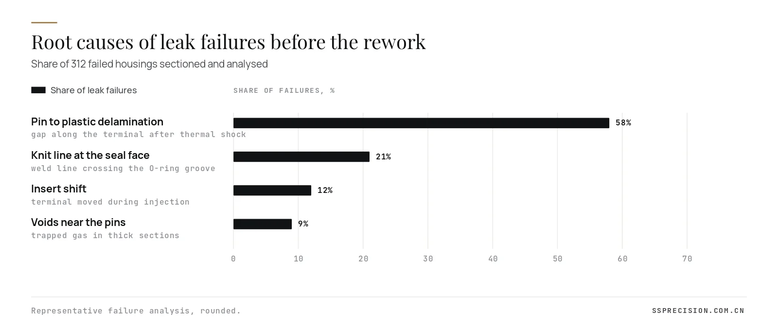
We asked for failed parts from the customer’s end of line test and from its thermal shock validation, 312 housings in total. Each was leak located with a dye penetrant and a helium sniffer, then sectioned through the leak path and examined under a microscope. The results pointed to four causes.
Delamination along the terminals
The largest cause was a gap between terminal and plastic that opened after thermal cycling. The terminals were flat and smooth through the housing wall, so the only thing holding plastic to metal was friction and a weak adhesion. Sections showed a residue of stamping oil on some terminals, and the terminals were entering the mold at shop temperature, so the melt skinned against cold metal before it could wet it.
A knit line across the seal face
The original gate sat on the connector side of the sensor housing. Melt flowed around the central sensing cavity and met again on the far side, forming a knit line that ran straight through the O-ring groove. Knit lines in glass-filled materials are weak because the fibres do not cross them, and under thermal stress this one cracked finely enough to leak past the O-ring.
Insert shift and voids
A smaller share of failures came from terminals that had moved during injection, thinning the plastic wall on one side, and from voids in a thick section near the terminal root where gas had been trapped. Both were symptoms of the original mold having only light support for the terminals and no venting at the last-filled region.
Redesigning the sensor housing system
The causes spanned the metal part, the plastic part, the mold and the process, so the fixes did too. The customer agreed to treat the housing, the lead frame and both tools as one system, and to let us build the stamping die and the insert mold together.
A lead frame designed to lock into the plastic
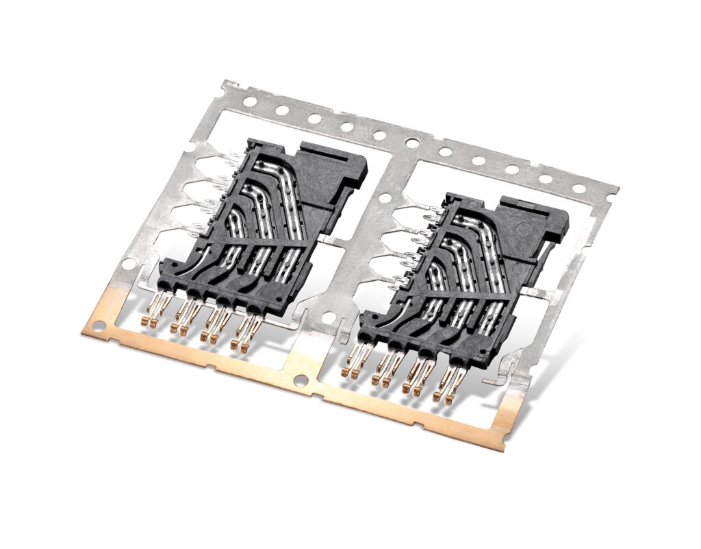
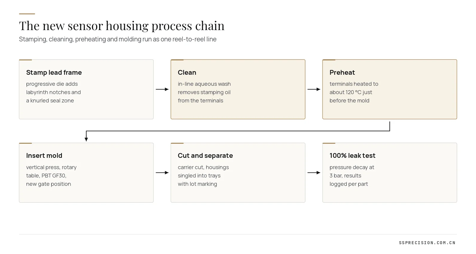
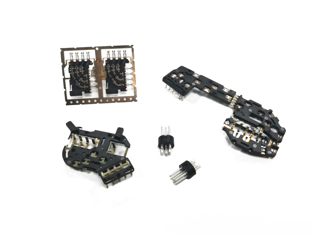
We redesigned the stamped terminals where they pass through the housing wall. Each terminal gained a pair of offset notches, forming a labyrinth that makes any leak path several times longer and gives the plastic a mechanical lock, and a coined knurl in the seal zone that increases the contact area and breaks any continuous gap. These features are formed in the progressive die at no extra cost per part. The terminals remain on a carrier strip so they reach the mold as a reel, in exact relative position.
Clean and preheated inserts
An in-line aqueous wash after stamping removes forming oil, and an induction preheater raises the terminals to about 120 °C just before they enter the mold. Hot inserts let the PBT melt wet the metal instead of freezing on contact, which improves both adhesion and the packing of the plastic around the notches. Preheating also reduced the thermal stress frozen into the plastic around the terminals, because the metal and plastic cool together.
A new 4-cavity insert mold
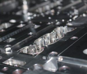
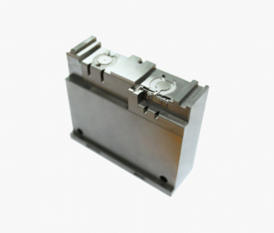
The new mold moved the gate to the end of the sensor housing opposite the connector, so melt flows along the housing axis and the knit line forms in the connector shroud, well away from the seal. Filling simulation confirmed the new position and showed where to add vents at the last-filled region near the terminal root. Each terminal is now held by a hardened locator at the carrier and by retractable support pins that withdraw after the cavity is mostly full, so the terminals cannot move but leave no holes in the finished wall. Cavity inserts are hardened H13 to resist the abrasive glass fibre around the thin sections.
The mold runs on a vertical press with a rotary table, loading the reel while the other half of the table is molding. That layout is standard for reel-to-reel insert molding: gravity keeps the inserts seated, and loading time is hidden inside the cycle. Our guide to preventing delamination in over-molding and insert molding covers these principles in more depth.
Material and drying
PBT is sensitive to moisture during processing. Wet PBT hydrolyses in the barrel, loses molecular weight and becomes brittle, which shows up as cracking at knit lines and around inserts. The previous process relied on hopper dryers with no moisture check. The new cell uses a desiccant dryer with dew point monitoring, and each material lot is checked for residual moisture before use, with the target below 0.02%. We also moved to a hydrolysis-resistant PBT GF30 grade, which the customer approved after checking its sensor element compatibility.
Containment while the new tools were built
New tools take weeks, and the customer was shipping every day. In the first week we proposed interim measures for the running process: an extra drying check on every PBT lot, a hot air preheat of loose terminals in a tray oven before hand loading, and cleaning the terminals in an ultrasonic bath to remove forming oil. The customer also added a thermal cycling screen on a sample from each lot. These steps did not remove the knit line cause, but they cut the failure rate after thermal cycling roughly in half within a month and bought the time needed to validate the permanent solution without shipping suspect parts.
Validation of the new sensor housing
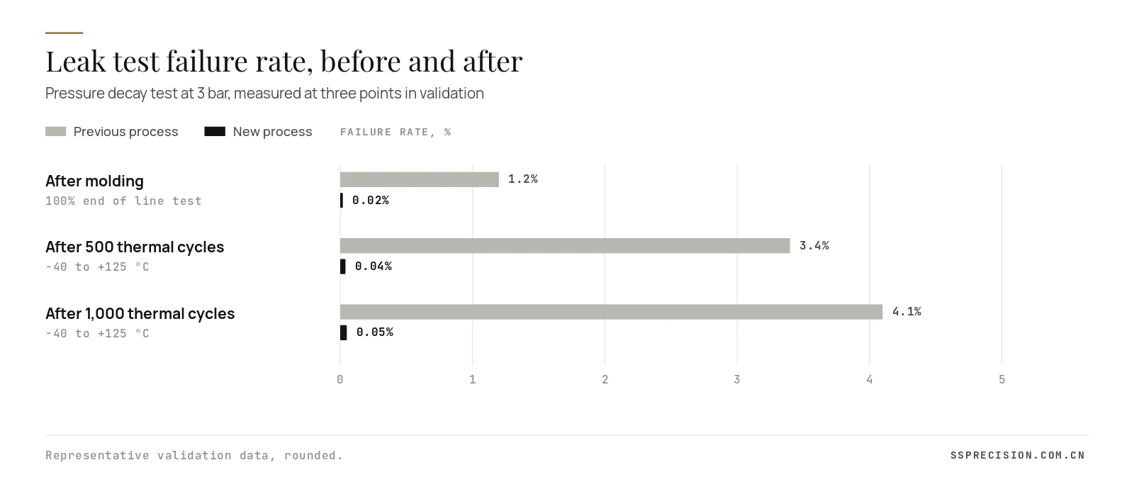
Validation followed the customer’s automotive test plan. Parts from all four cavities went through 1,000 thermal shock cycles from −40 to +125 °C, followed by a pressure decay test at 3 bar, then by sectioning of samples to inspect the terminal interface. Additional parts went through vibration, pressure pulsation and fluid immersion in coolant and oil. We also sectioned parts at the start, middle and end of each validation lot to confirm that the interface looked the same throughout.
Sections of the new housings showed the plastic filling the labyrinth notches completely and bonded along the knurled seal zone, with no gap after 1,000 cycles. The knit line now sits in the connector shroud, where it carries no seal function, and tensile tests of the shroud showed ample margin.
Sensor housing results in production
| Measure | Previous process | New process |
|---|---|---|
| Leak failures after molding | 1.2% | 0.02% |
| Leak failures after 1,000 thermal cycles | 4.1% | 0.05% |
| Terminal position in housing | ±0.12 mm | ±0.05 mm |
| Cycle time | 28 s | 24 s |
| Insert loading | loose terminals, placed by hand | reel-to-reel, automatic |
| Field returns for leakage | several per quarter | none since launch of the change |
Figures rounded from validation and the first nine months of production.
The cycle time fell even though the process added cleaning and preheating, because the hot inserts allowed a shorter hold time and the reel removed hand loading. The customer now runs the sensor housing on two cells of the same design and has applied the same lead frame features to a second sensor family.
Sensor housing project timeline
- Weeks 1 to 2: failure analysis of 312 parts, root cause report, containment advice for the running production.
- Weeks 3 to 4: lead frame redesign, filling simulation, new gate and venting, design review with the customer’s product and quality teams.
- Weeks 5 to 9: progressive die and insert mold built in parallel; wash and preheat units specified with the customer’s automation partner.
- Weeks 10 to 12: tryout, first article inspection, validation lots from all four cavities.
- Weeks 13 to 20: customer validation testing and approval, production release.
Lessons for any insert-molded sensor housing
- Design the metal for the plastic. Notches, holes and knurls give the plastic something to hold and lengthen any leak path. They cost nothing in a progressive die.
- Keep knit lines away from seals. Gate location decides where the weak line forms; put it where it carries no load and no seal.
- Insert condition is a process parameter. Clean, preheated inserts bond; oily, cold inserts do not.
- Hold the inserts, then let go. Retractable support pins fix the terminals during filling without leaving holes.
- Dry the resin and prove it. For PBT and PA, dew point monitoring and moisture checks prevent brittle interfaces.
- Test after thermal cycling, not only after molding. Most interface leaks only appear after the part has been cycled.
If a sealed sensor housing or connector passes leak tests when new but fails after thermal cycling, look at the metal to plastic interface first. A handful of sectioned failures usually tells the story within a week.
What a leaking sensor housing really costs
A 4% failure rate at end of line looks like a scrap problem, and scrap was indeed expensive: every rejected sensor housing had already absorbed the terminals, the molding and often the sensing element. The larger cost was elsewhere. Parts that pass at end of line but leak after thermal cycling fail in the vehicle, where a single field return triggers containment, sorting of stock at the customer, an 8D report and sometimes a recall assessment. The customer had also added a second leak test station and a 100% visual check of the seal groove to catch knit line cracks, which added labour and floor space to every housing produced. Removing the root causes removed all of those costs together.
Inspection and traceability in the new cell
Every sensor housing now carries a laser-marked date and cavity code, and its leak test result is stored against that code. The press controller logs insert preheat temperature, melt temperature, injection pressure curve and hold time for every shot, and parts from any shot outside its window are diverted automatically. Terminal position is measured on a CMM at the start of each lot and after any mold maintenance, and two sensor housings per cavity per week are sectioned through the terminals to confirm that the interface still looks as it did in validation. When a question arises from the field, the customer can trace a part to the shot, the cavity, the material lot and the reel of terminals it was molded from.
Sensor housing design checklist
Before releasing a new insert-molded sensor housing for tooling, we now review these points with the customer:
- Locking features on every terminal where it passes through a sealed wall, sized for the plastic flow.
- A gate position that places the knit line away from O-ring grooves, sealing faces and thin walls.
- Uniform wall thickness around the terminals, with no thick pockets that trap gas or sink.
- Support and locating features on the carrier so terminals can be held during filling.
- Material choice for the fluid, temperature and humidity of the application, including hydrolysis resistance.
- A validation plan that tests leak tightness after thermal cycling, not only when new.
Why stamping and molding belong together
Many leak problems start in the gap between two suppliers: one stamps the terminals, another molds the housing, and neither owns the interface. In this project, owning both the progressive die and the insert mold let us put features into the lead frame specifically for the mold, choose carrier geometry that the mold could locate on precisely, and adjust both tools during tryout without a round of change requests. For any sensor housing or connector where the metal to plastic interface is critical, we recommend designing the two tools as one project.
Leaks, delamination or cracking on an insert-molded part?Send failed samples or a description with your test conditions. We will propose a failure analysis plan and, if needed, the tooling changes.
Request a quoteInsert molding at SSP
We design and build insert and overmold tools for connectors, sensor housings, busbar assemblies and electrical components, and the progressive dies that make the metal inserts. Our over-molding and insert molding page describes the process range, and the injection mold page covers our wider mold building. For related case studies, see how we rebuilt a terminal stamping die for 1,200 strokes per minute. Background on the process is available in this introduction to insert molding.
Sensor housing FAQ
Why do insert-molded sensor housings leak?
The most common causes are delamination between terminals and plastic after thermal cycling, knit lines crossing seal areas, inserts that move during injection, and voids near the inserts. Oily or cold inserts and wet resin make delamination more likely.
How do you stop plastic separating from metal terminals?
Add mechanical locking features such as notches, holes or knurls to the terminals, clean them of stamping oil, preheat them before molding and use a well dried, hydrolysis-resistant resin. Special surface treatments or adhesion promoters can help in demanding cases.
What material is used for automotive sensor housings?
Glass-filled PBT and PA66 are the most common, with PPS used for higher temperatures and aggressive fluids. Hydrolysis-resistant grades are preferred for coolant and humid environments.
What leak test is used for a sensor housing?
Pressure decay or helium leak testing at a defined pressure is typical, performed after molding and repeated after thermal shock, vibration and fluid exposure during validation, with sectioning to confirm the interface.
Should terminals be insert molded from a reel?
For medium and high volumes, yes. Reel-to-reel insert molding keeps terminals in exact relative position on the carrier, allows automatic loading on vertical rotary presses and makes cleaning and preheating easy to integrate.
Customer name, part details and some figures are anonymized or rounded to protect confidentiality.