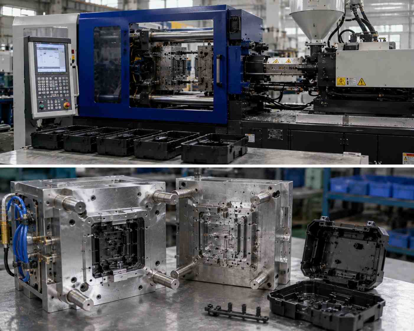
When production managers try to improve a plastic injection molding run, they usually zero in on machine related stuff like increasing injection velocity, or fast forwarding robotic part extraction. Still, the real bottleneck in plastic processing stays pretty thermal, and kind of stubborn. Molten resin gets into the mold tool at extremely high temperatures, and it just cannot safely exit until it cools past its specific heat deflection point. If you push an ejection too early while the core is still soft and kind of liquid-like, the component will sag , twist, or even collapse completely from its own structural load. @wiki info
Why Cooling Controls the Production Clock?
If you examine a typical injection molding schedule as a whole, the economic weight of Mold Cycle Time optimization becomes oddly clear. Mechanical moves, resin dosing, and high pressure cavity packing take up only small portions of the total run time. The thermal solidification step is the actual time eater for high-volume manufacturing
- Resin injection phase: uses roughly 10% to 15% of the operational clock
- Packing and holding phase: steals about 10% to 20% of the setup timeline to reduce plastic shrinkage
- Ejection and clamp movements: generally grabs 5% to 10% of the active cycle
- Cooling phase: consistently devours around 50% to 70% of the entire processing window
So since cooling is the dominant bottleneck, slicing a tiny fraction of a second from the filling stage usually delivers nearly no money back. Real cycle breakthroughs only show up when you aggressively improve the way heat leaves the mold cavity, not just how fast you fill it.
The Mechanics of Thermal Conductivity in Tooling
Getting strong, fast heat shedding really starts with a close look at a big Mold Design Impact. Like, what the mold tool is actually made of, not just how it looks. In the past, people leaned on traditional tool steels because they bring top level wear resistance, especially when you’re dealing with abrasive resins. But those same steels can become this kind of thermal logjam, when you need heat to move away from the hot plastic quickly.
- Standard P20 Tool Steel: gives really solid surface durability, yet it has low thermal conductivity (about 26 W/m·K).
- Premium H13 Steel: brings strong impact durability for long runs, but its thermal conduction stays moderate (around 24 W/m·K).
- Specialized Aluminum Alloys: can move heat amazingly well, sometimes up to 160 W/m·K, but they tend to fatigue faster under high clamping forces, so they usually end up being more for low-volume prototype work.
- Advanced Copper-Beryllium Formulations: can push thermal conductivity dramatically higher, up to 130 W/m·K, while still keeping the kind of mechanical hardness you need, to survive millions of cycles.
To optimize how heat leaves the mold cavity, engineering teams must evaluate the raw material properties of the tooling core. Traditional options favor structural durability over thermal efficiency, creating an intentional cooling bottleneck.
| Tooling Material | Thermal Conductivity (W/m·K) | Structural Hardness (HRC) | Ideal Production Lifecycle Tier |
| P20 Tool Steel | ~26 | 28–32 | Standard baseline low-to-medium volume molding runs |
| H13 Tool Steel | ~24 | 48–52 | High-impact, extreme longevity abrasive resin operations |
| QC-10 Aluminum | ~160 | 15–18 | Accelerated, low-pressure rapid prototyping cycles |
| Copper-Beryllium | ~130 | 36–40 | High-velocity thermal insertion for localized deep hotspots |
Traditional Straight-Drilled vs. Conformal Cooling Channels
For decades, mold makers had to fall back on these long industrial gun drills to cut fluid channels through solid steel mold blocks. It worked, sure, for basic blocky shapes, but the straight drilled lines are kind of boxed in by geometry rules. They cannot bend, curve, or loop around the detailed areas of a part, not really. Because of that you often get uneven cooling , with deep pockets of trapped heat sitting in the more complex regions, while the thin outer walls cool down almost immediately, like too fast.
Nowadays, high speed production has pushed more and more toward conformal cooling channels. They are made using advanced metal 3D printing methods such as Direct Metal Laser Sintering (DMLS) , where the channels are built layer-by-layer to match the exact contours of the part cavity. In practice, that means the coolant stays at a consistent, exact spacing from the hot plastic face even when the geometry gets messy—think deep ribs, tall bosses, and those sweeping curves that would normally force you to compromise.
Designing for Fluid Turbulence and Reynolds Number
To achieve rapid Injection Mold Cooling, you cannot just let water drift slowly through internal mold lines. If the flow speed is too low, the water tends to move in smooth, parallel bands. That behavior is called laminar flow. In a laminar setup, the outermost band quickly grabs heat from the channel walls and then it basically behaves like an insulating layer, keeping the cooler core water from pulling out meaningful energy.
So, to break that effect, mold engineers design for turbulent flow, where the water is mixed in an energetic way and continuously sends fresh, cooler fluid against the hot steel surfaces. That fluid state is tracked using the Reynolds number (Re), which is a dimensionless measure tied to friction and flow behavior. To unlock the best possible heat extraction performance, the cooling system has to exceed these clear operating limits:
- Laminar Flow Region (Re less than 2,100): fluid moves smoothly , pretty much like it should, and the heat transfer rates sink to their absolute minimum
- Transition Zone (Re between 2,100 and 4,000): this is where it gets messy, unstable fluid mixing that makes cooling zones that are more random than you want, uneven too.
- Fully Turbulent Flow Region (Re greater than 4,000): intense fluid churning , which maximizes the thermal extraction in a very aggressive way
- Optimal Engineering Target (Re between 4,000 and 10,000): delivers the top thermal efficiency while avoiding too much pump wear on the system
Achieving rapid thermal extraction requires a precise calculation of internal fluid friction. Letting water lazily drift through a cooling circuit allows an insulating boundary layer to form, severely capping heat transfer rates.
| Fluid Flow Regime | Reynolds Number (Re) | Inner Channel Fluid Behavior | Thermal Extraction Efficiency |
| Laminar Flow | Less than 2,100 | Smooth, parallel isolated liquid layers | Absolute Minimum (Creates thermal barrier) |
| Transition Zone | 2,100 to 4,000 | Unstable, shifting swirling currents | Highly Unpredictable (Causes tool variation) |
| Fully Turbulent | Greater than 4,000 | Intense, chaotic molecule mixing | Maximum (Constantly throws cold fluid outward) |
Minimizing Part Warpage and Thermal Residual Stress
A properly engineered thermal management setup does more than just provide a big Cycle Time Reduction; it also acts like your first line of defense against expensive structural warpage. When one side of a molded plastic component cools much slower than the opposing face, the two surfaces shrink at totally different paces. That unequal contraction generates lasting internal thermal stresses , and these stresses start pulling, twisting, and warping the part as soon as it comes out of the mold.
By making sure the entire cavity surface area drops in temperature uniformly, conformal arrangements reduce localized shrinkage differences to nearly zero. The part stays flat, circular features stay aligned, and snap-fit assemblies click together without constant secondary manual straightening, or the need for extra long cooling fixtures.
High-Conductivity Inserts for Localized Hotspots
In highly intricate molds, there are often really tight geometric limitations where printing custom 3D fluid channels just isn’t doable , not in any practical sense. In those constricted zones, seasoned toolmakers usually rely on high conductivity metal inserts as a kind of thermal shortcuts.
These high-performance metal blocks are pushed straight into deep core pins or snug rib junctions. Basically they catch the trapped heat from the hard-to-reach plastic parts, then guide it out toward the main water lines. That removes localized hotspots without creating extra risk of water leaks near the delicate ejector pin routes, so you don’t get surprises later.
Strategic Gate Design and Its Thermal Footprint
The actual position and dimensions of an injection gate leave a big imprint on the overall thermal balance of a production tool. The gate size has to be right , so material flows correctly and then it freezes off quickly at the close of the holding cycle.
- Undersized Gates: they choke flow, which raises friction heat. That heat can degrade the resin and then cooling tends to drag on longer than it should.
- Oversized Gates: they keep the entry region in a molten state for too long, so the machine must extend the packing cycle just to stop backflow.
- Optimized Gate Configurations: the gate seals shut precisely once the part cavity is fully packed. Then the machine shifts to cooling right away, with no wasted time.
Advanced Maintenance Protocols for Scale Mitigation
Even the most sophisticated cooling layout will slowly degrade if the plant water supply is not carefully monitored. Industrial processing water is filled with microscopic mineral compounds that naturally precipitate out once it’s exposed to intense mechanical heat. Over months of high-velocity operations the minerals form a hard scale layer along the inner channel walls, and that scale ends up acting like a kind of insulating blanket. It chokes water flow, and thermal cycle times start to steadily creep upward, which is the part nobody likes to see. Modern production plants run regular chemical flushing routines to strip away scale deposits, checking flow meters weekly so turbulent fluid velocities stay completely uninhibited.
Sourcing Precision Tooling: High-Efficiency Injection Molds
To stay globally competitive in high-volume plastics processing, there has to be a strong focus on the Mold Efficiency China supply chains. High-end mold manufacturers have invested a lot in advanced industrial technology, like multi-axis CNC machining, deep-hole gun drilling, and industrial metal 3D printing. By partnering with mold builders who use advanced computational fluid dynamics (CFD) to map and test internal thermal flow patterns before cutting any steel, OEMs can secure fast production cycles and long tool life, even from that very first sample shot.
Technical Sourcing Resources
SSP Precision is an ISO 9001 & IATF 16949 certified manufacturer delivering end-to-end precision solutions, from design and prototyping to high‑volume production, for the automotive, medical, electronics, aerospace, and industrial sectors. We handle every stage in‑house – DFM engineering, rapid prototyping, CNC machining, EDM, grinding, and global logistics – to manufacture the tooling that makes your parts and the parts themselves.
What we build and supply: visit our sites: https://ssprecision.com.cn/
- Stamping dies manufacturing and stamping die parts – high‑precision transfer stamping dies and progressive/compound dies for volume metal stamping.
- Injection molding and injection mold – custom injection molds for plastic components, including single‑, multi‑cavity, and over‑molding & insert‑molding tools that combine metal and plastic in one part.
- Specialty molded components – eco‑friendly green mold parts and microscopic medical micro‑molded parts.
- Precision metal and plastic end‑use parts – high‑volume serial production of precision products (metal stampings, plastic moldings) with full PPAP traceability.
- Tooling spare parts manufacturing & – tooling spare parts (punches, inserts, ejector pins) and precision robotics spare parts to keep your production running.
Frequently Asked Questions
How much can conformal cooling really cut down mold cycle times vs the usual drilling way?
In practice conformal cooling often trims cooling steps by something like 20% to 50%. Since cooling itself is about 50% to 70% of the injection molding cycle, adding conformal channels commonly gives you a 15% to 35% overall cycle time drop, and that can really bump up parts per day.
What are the main tells that a mold’s cooling passages are starting to collect scale or buildup?
The first giveaway tends to be a slow, steady creep in your cycle times, over weeks ,or months. You may also notice more part warpage, or other dimensional issues, plus a drop in fluid flow rate that’s pretty measurable. Often there’s also a wider-than-usual temperature spread between the water inlet and outlet, like the system can’t exchange heat the same way anymore.
Why not just make the entire mold out of high-conductivity copper so it stays super cold and moves heat fast?
Copper alloys absolutely have top tier thermal performance, but they don’t bring the physical toughness and wear resistance you want from dedicated tool steels such as H13 or P20. A full copper mold would tend to deform under high clamping pressures, and it would wear faster from abrasive contact, especially with glass-filled plastic resins. Using copper as targeted inserts, rather than the whole structure, gives a more balanced setup rapid cooling exactly where needed, supported by steel for stiffness and durability.
🔍 Read More – Intelligence That Protects Your Production Line
-
Stamping Die Cost Drivers: What Impacts Your Price – A single-station die costs $3,000–$8,000, while a progressive die can hit $120,000+—here’s the breakdown of 7 key cost drivers, from material selection to EDM hours, with real China vs. Western pricing data.
-
Injection molding: Hot Runner Vs Cold Runner – Hot runners add 30–50% to upfront tooling cost but can slash cycle times by 40% and eliminate material waste—here’s how to weigh the trade-off for your production volume.
-
Injection Molding Tolerances (With Precision Chart) – Tightening a tolerance from IT7 to IT3 can triple your mold cost—here’s the precision grade chart, material-specific shrinkage data, and how to specify only what your design actually needs.
-
How Much Does an Injection Mold Cost in China? – A Class 101 production mold runs $15,000–$60,000+, while a prototype tool can cost under $4,000—here’s the SPI classification breakdown and the 5 key cost drivers that shape your final quote.
-
Holding ±0.001 mm: Thermal Control in Precision CNC – A 2°C temperature swing can add 7 microns of error—here’s how thermal control architecture, spindle warm-up protocols, and granite bases make the difference between hitting tolerance and scrapping the part.
-
D2 vs DC53 Tool Steel: Which is Best for Stamping? – D2 has been the industry standard, but DC53 offers twice the toughness and better machinability—here’s the metallurgical data to decide which alloy delivers lower total cost of ownership for your stamping application.
-
Sourcing Ejector Pins & Mold Components in China – DIN 1530 ejector pins at $5.80–$8.60 per piece with ±0.002mm grinding precision and 7–15 day lead times.
-
Sourcing Ejector Pins & Mold Components in China – DIN 1530 ejector pins at $5.80–$8.60 per piece with ±0.002mm grinding precision and 7–15 day lead times.