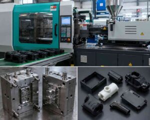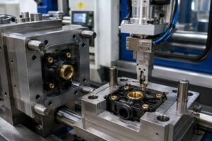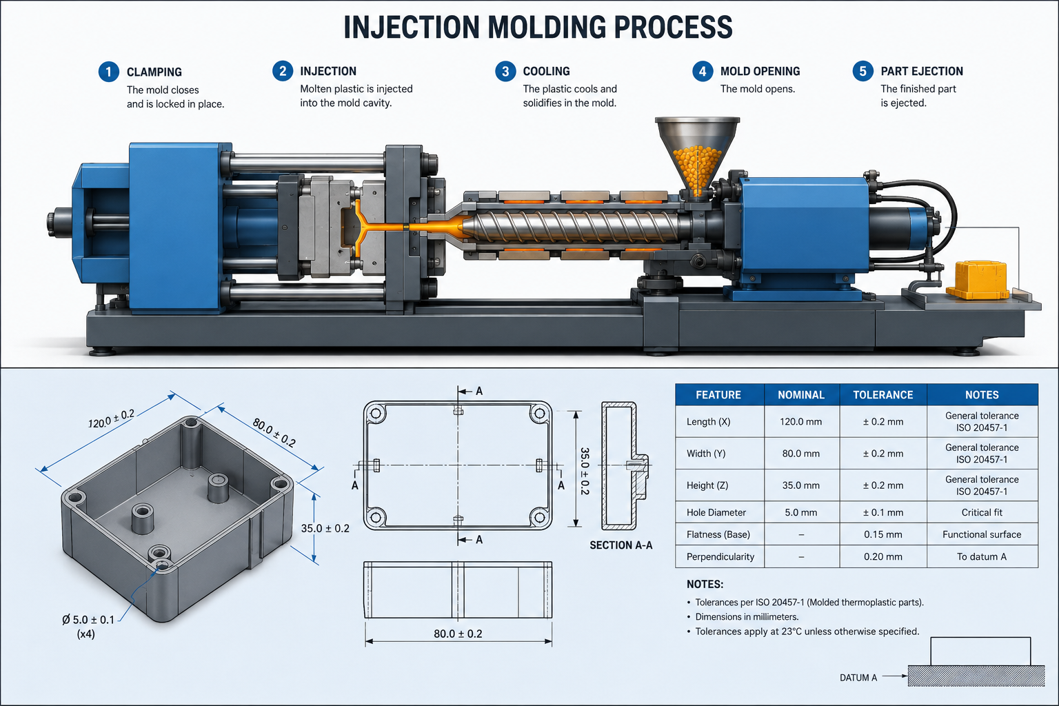
Understanding Injection Molding Tolerance is, honestly, fundamental for making plastic parts that actually fit, assemble, and don’t end up costing you more than they should. Whether you’re designing a medical device component that needs ±0.005mm precision, or you’re working on a consumer product housing with standard tolerances, the allowed dimensional deviation matters a lot. It will directly affect mold design decisions, the way you choose materials, and basically the production cost too. This guide gives a fairly comprehensive technical breakdown of injection molding tolerance standards, precision grades, and some material- specific considerations. With 15+ years in precision manufacturing, 50+ engineering resins available, and ±0.005mm micro-molding capabilities, SSPrecision delivers high-performance custom injection molded parts to 30+ countries across the globe.
Core Engineering Objectives:
• Understand how nominal dimension, material shrinkage, and achievable tolerance grades connect together.
• See that when tolerances get tighter the mold manufacturing costs can climb, like exponentially fast, and not in a linear way.
• Navigate international tolerance approaches, including ISO 20457, DIN 16742, and GB/T 14486-2008.
Technical Specification & Precision Grades Matrix
Injection molding tolerances are classified into precision grades based on nominal dimension ranges.
| Precision Grade | 1.0 – 3.2 mm | 3.2 – 6.3 mm | 6.3 – 10 mm | 10 – 18 mm | 18 – 30 mm |
| IT3 (Ultra-Precision) | ±0.02 mm | ±0.03 mm | ±0.04 mm | ±0.05 mm | ±0.06 mm |
| IT5 (High Precision) | ±0.06 mm | ±0.08 mm | ±0.10 mm | ±0.12 mm | ±0.15 mm |
| IT7 (Standard) | ±0.12 mm | ±0.16 mm | ±0.20 mm | ±0.24 mm | ±0.28 mm |
| IT9 (Commercial) | ±0.24 mm | ±0.32 mm | ±0.40 mm | ±0.48 mm | ±0.56 mm |
Based on GB/T 14486-2008. SSPrecision routinely achieves ±0.005mm tolerances on micro-molded parts with mold cavity manufacturing held to ±0.005mm.
Standard Injection Molding Tolerance Benchmarks
Understanding typical tolerance ranges helps designers set realistic expectations.
| Typical Application Examples (for this size range) | Dimension Range (mm) | Commercial (±mm) | Precision (±mm) |
|---|---|---|---|
| Small connectors, clips, micro-gears, LED lenses | < 25 | 0.15 | 0.05 |
| Electronic housings, knobs, bottle caps, cable grommets | 25 – 50 | 0.20 | 0.08 |
| Handheld device shells, switch bezels, small brackets | 50 – 75 | 0.25 | 0.10 |
| Appliance buttons, sensor bodies, compact enclosures | 75 – 100 | 0.30 | 0.12 |
| Power tool handles, instrument panels, mid-sized covers | 100 – 125 | 0.35 | 0.15 |
| Dashboard components, printer housings, medical device enclosures | 125 – 150 | 0.40 | 0.18 |
| Laptop bezels, center console parts, mid-sized structural brackets | 150 – 175 | 0.45 | 0.20 |
| Appliance doors, large bezels, external automotive trim | 175 – 200 | 0.50 | 0.25 |
| Equipment housings, furniture connectors, fluid reservoirs | 200 – 250 | 0.60 | 0.30 |
| Automotive bumpers (sections), large brackets, material handling trays | 250 – 300 | 0.70 | 0.35 |
| Exterior body trim, large panels, industrial guard covers | 300 – 350 | 0.80 | 0.40 |
| Pallet components, large containers, bin walls | 350 – 400 | 0.90 | 0.45 |
| Oversized housings, industrial tanks, structural cabinetry | > 400 | 1.00 | 0.50 |
SSPrecision maintains mold manufacturing tolerances to ±0.005mm on critical features, with wire EDM achieving ±0.003mm.
Step-by-Step Tolerance Specification Protocol
Initial Parameter Identification: Start by spotting the critical functional dimensions on your part. Think about mating surfaces, bearing journals, snap-fit geometry, and sealing areas. Write down the nominal dimension, your material selection (because that sets the shrinkage behavior), and the overall part geometry. Tool-controlled dimensions usually allow tighter tolerances compared to free dimensions, which get influenced more by shrinkage.
Core System Execution & Tolerance Calculation: First, estimate expected shrinkage from the material shrinkage range. ABS typically shrinks 0.5–0.8%, PC shrinks 0.6–0.9%, and PP often shrinks 1.5–2.0%. Then use the relation: Mold Dimension = Part Dimension × (1 + Shrinkage Rate). After that, select the tolerance grade you need from ISO 20457 based on the nominal dimension range.
Compliance Verification & Quality Sign-Off: We need to verify that the tolerances do comply with ISO 20457:2018, DIN 16742, or GB/T 14486-2008. Next, run Moldflow simulation to forecast fill patterns , the weld lines, and also the warpage behavior. Then do a First Article Inspection, and use CMM to confirm every critical dimension before we allow production release, ok.
Deep-Dive Technical Variable & Risk Analysis
Material Shrinkage & Variability: Shrinkage is basically the biggest single contributor to tolerance drift. Crystalline feedstock, like nylon and PP, tends to pull back more (about 1.5–2.0%) and it also shows higher inconsistency compared with amorphous grades such as ABS and PC, which usually land around 0.5–0.9%. For PA assemblies, moisture uptake during storage can lead to after-mold dimensional shifts.
Warpage & Thermal Expansion: Uneven cooling generates internal stresses, those stresses then drive warpage, especially where wall thickness isn’t balanced. SSPrecision keeps mold temperature uniform, within ±1°C across the cavities, so distortion is less likely , and still the geometry stays steadier.
Process Stability: Injection molding repeatability will make or break the final tolerance. Typical presses show weight repeatability errors near 1%, precision class equipment gets to about 0.5%, and ultra-precision machines can reach below 0.3%.
Key Engineering Compliance Standard
- Standard Code: ISO 20457:2018 / DIN 16742 / GB/T 14486-2008
- Critical Threshold: For precision applications, mold cavity machining must be controlled at ±0.005mm, no “close enough”. Medical device tolerances usually sit in a band from ±0.003mm to ±0.01mm.
- Operational Impact: If this is violated, you can see part rejection, assembly failure, or real functional defects. Rework, or mold change work, often pushes timelines by 2–6 weeks.
Critical Component Breakdown & Material Science
Mold Steel & Cavity Manufacturing: Mold cavities are machined from P20, H13, or S136 steel, using CNC machining, EDM, and wire EDM . The critical features are finished to ±0.005mm on CNC, and ±0.003mm on wire EDM (kinda tight yes). Hardened steel grades are used to keep dimensional stability even across millions of cycles, that matters in real production runs.
Cooling System Design: Conformal cooling channels are laid out to keep the mold temperature more uniform, so warpage gets minimized. Vent channels are machined to about 0.003–0.008mm depth, to stop trapped air, while also controlling flash and similar defects that like to sneak in.
Material Selection: SSPrecision offers 50+ engineering grade resins such as ABS, PC, PA66, POM, PEEK, TPE, and LSR, and they’re matched to mechanical, thermal, plus regulatory needs. In other words it’s not just “choose a plastic”, it’s choose a behaving plastic.
Structural Integrity, Mold Design & Boundary Limits
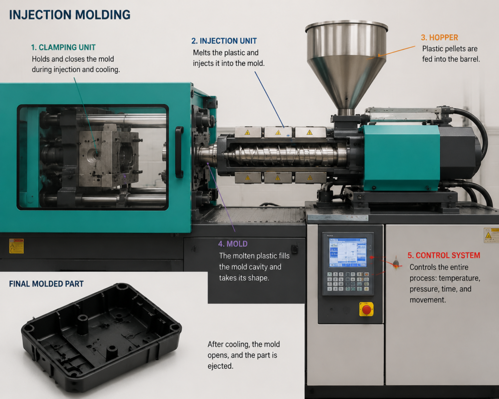
Static & Dynamic Load Capacities: Injection molding machines are typically rated by clamping force (50–5,000 tons). The mold itself has to survive injection pressures up to around 2,000 bar, without deflection going past the tolerance limits, or you end up chasing problems later.
Pressure Containment Limits: Hydraulic and toggle clamping systems hold the mold closed under high injection pressure. If the clamping force is insufficient, flash shows up, and then you’re stuck cleaning edges. Not fun.
Welding & NDT Standards: Mold component welding follows AWS D1.1. NDT methods, like dye penetrant testing and magnetic particle inspection, help catch cracks or voids before they become bigger issues. Basically it’s a quality check with receipts.
Architecture, Controls & Process Monitoring
Control Loop Topology: Closed loop control systems track injection pressure, screw position, and mold temperature in real time. Servo valves then adjust hydraulic pressure every millisecond, to keep fill profiles consistent. That’s the whole idea, steady output.
Communication Protocols: The machines support Ethernet/IP, Profinet, and OPC UA so SCADA integration stays smooth. With real time monitoring, you can collect SPC data, and troubleshoot trends instead of reacting randomly.
VFD Sizing: Variable Frequency Drives run screw rotation control. Active front-end drives can reduce harmonic distortion to below 5% THD, keeping the drive behavior cleaner.
Operational Maintenance Matrix
Daily diagnostics for the process: make sure the mold temperature stays pretty steady, uniformity check (±1°C) , keep an eye on injection pressure, then do a quick visual inspection for flash or surface defects.
Quarterly intervention (every 2,000 hours): mold cleaning, vent channel inspection (0.003–0.008mm) , check the parting line surface, and run hydraulic oil filtration.
Annual refit (8,000 hours): verify mold steel hardness, plan ejector pin replacement, descaling the cooling channels, and recalibrate the control system.
Real-World Application & Engineering Case Proof
Case Study: Medical Micro-Component Tolerance Optimization
The industrial challenge: a medical device manufacturer needed 250,000 connector housings with ±0.005mm tolerances. Flash-related rejects were sitting at 4.2% , and the yield loss was not small.
Custom engineering response: SSPrecision engineers traced the issue to parting line tolerance drift plus venting inadequacy. The vent channels were re-machined to 0.003 — 0.008mm depth, and they added vacuum-assisted venting. They also used segmented mold-temperature regulation to keep ±1°C uniformity across all cavities.
The quantifiable outcome: Flash-related rejects dropped from 4.2% down to under 0.6%. Fill pressure came down by 20% thanks to the vacuum-assisted venting. And the ±0.005mm tolerances stayed consistent through the full production run. Overall scrap rates were reduced by 70–85% , which basically changed the economics.
Our other services – SSP
SSP Precision is an ISO 9001 & IATF 16949 certified manufacturer delivering end-to-end precision solutions, from design and prototyping to high‑volume production, for the automotive, medical, electronics, aerospace, and industrial sectors. We handle every stage in‑house – DFM engineering, rapid prototyping, CNC machining, EDM, grinding, and global logistics – to manufacture the tooling that makes your parts and the parts themselves.
What we build and supply: visit our sites: https://ssprecision.com.cn/
- Stamping dies manufacturing and stamping die parts – high‑precision transfer stamping dies and progressive/compound dies for volume metal stamping.
- Injection molding and injection mold – custom injection molds for plastic components, including single‑, multi‑cavity, and over‑molding & insert‑molding tools that combine metal and plastic in one part.
- Specialty molded components – eco‑friendly green mold parts and microscopic medical micro‑molded parts.
- Precision metal and plastic end‑use parts – high‑volume serial production of precision products (metal stampings, plastic moldings) with full PPAP traceability.
- Tooling spare parts manufacturing & – tooling spare parts (punches, inserts, ejector pins) and precision robotics spare parts to keep your production running.
Frequently Asked Sourcing & Procurement Questions
What’s the tightest tolerance you can really get with injection molding?
At SSPrecision we routinely hit ±0.005mm on micro-molded parts , and for ultra-precision stuff ±0.003mm can be done on the really critical features. But yeah, tolerances aren’t magic, they’re strongly material-dependent, because crystalline materials tend to show more shrinkage variability compared with amorphous ones.
How does material choice change injection molding tolerances, though?
For example, ABS and PC typically shrink around 0.5–0.9%, while PP is more like 1.5–2.0%. That means higher-shrinkage materials generally need more mold compensation, and you’ll often see more day-to-day or batch-to-batch variability. On top of that, crystalline materials can take on moisture, which then causes dimensional drift after molding, so the part might not “settle” the way you expected at first.
What about the cost impact when you specify tighter tolerances?
Medium tolerance parts usually come in at about 1.7× the normal cost, and fine tolerance parts can run 3× normal. It’s not only because “tight” is hard, it’s also because precision work usually needs specialized equipment, hardened mold steels, plus tighter process controls. In practice it’s best to specify the tight tolerances only on the critical functional features, and keep the rest looser when you can.
What’s the difference between tool-controlled and free dimensions?
Tool-controlled dimensions are basically “mold cavity steel says so” and they tend to be more stable. Free dimensions are more of a follower type, they’re driven by shrinkage and deformation, so they can wander more. That’s why the tolerance agreement should explicitly state which dimensions are tool-related versus which are free, otherwise you can end up with disagreements later on.
Read More – Intelligence That Protects Your Production Line
-
How Much Does an Injection Mold Cost in China? – A Class 101 production mold runs $15,000–$60,000+, while a prototype tool can cost under $4,000—here’s the SPI classification breakdown and the 5 key cost drivers that shape your final quote.
-
Holding ±0.001 mm: Thermal Control in Precision CNC – A 2°C temperature swing can add 7 microns of error—here’s how thermal control architecture, spindle warm-up protocols, and granite bases make the difference between hitting tolerance and scrapping the part.
-
D2 vs DC53 Tool Steel: Which is Best for Stamping? – D2 has been the industry standard, but DC53 offers twice the toughness and better machinability—here’s the metallurgical data to decide which alloy delivers lower total cost of ownership for your stamping application.
-
How to Track & Prevent Tool Wear in Progressive Dies – Acoustic sensors, tonnage monitoring, and carbide inserts can push die life beyond 200,000 strokes—here’s the data on tracking wear thresholds before they become catastrophic failures.
-
Insert Dies Vs. Solid Dies: Maintenance & Cost Analysis – Insert dies cost 10–20% of their original price to repair, while solid dies run 40–70%—here’s the data on downtime, spare parts strategy, and which design wins for high-volume stamping.
-
Injection Molding Guide: Costs, Materials, Process, and Mold Tooling – A prototype mold can cost $3,000, while a high-volume production mold runs $80,000+—here’s how to match tooling class to real production volume and avoid overpaying for steel.
-
Injection molding: Hot Runner Vs Cold Runner – Hot runners add 30–50% to upfront tooling cost but can slash cycle times by 40% and eliminate material waste—here’s how to weigh the trade-off for your production volume.
-
China Fiber Optic Connectors | Injection Molding Precision Parts Manufacturer Company – Fiber optic connector housings demand ±0.01 mm tolerances on critical alignment features—here’s the material selection guide, cavity configuration data, and quality control protocols for precision optical components.
-
Reducing Cycle Time Through Better Mold Cooling – Cooling eats 50–70% of your cycle time—here’s how conformal cooling channels, turbulent flow design, and high-conductivity inserts can slash cooling time by 20–50% and cut overall cycle time by 15–35%.
-
Multi-Cavity Injection Molds: Cost & Efficiency Breakdown – A 4-cavity hot runner mold costs 2.5–4x a single-cavity tool but delivers proportionally larger per-part cost savings at volume.